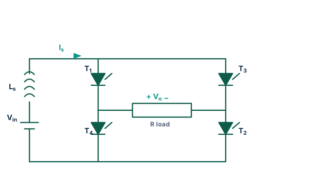
What is a single-phase current-source inverter (CSI)?
A current-source inverter (CSI) is the dual of the voltage-source inverter. Instead of a large capacitor holding a stiff DC voltage, a large series inductor Ls holds a stiff DC current Id. The four-device H-bridge then steers this constant current through the load: diagonal pair T1-T2 sends +Id and pair T3-T4 sends −Id, so the output is a square-wave current, not a square-wave voltage.
Output current, fundamental and RMS
For full square-wave operation the load current alternates between +Id and −Id every half-cycle:
Only odd harmonics (3rd, 5th, 7th…) are present. This simulator forces the exact switching current and integrates the actual load network — the load resistance in series with any inductance, in parallel with an optional output capacitor — so every waveform, RMS and THD is exact.
Notch (pulse-width) control of the fundamental (topic-specific)
The DC-link current cannot change quickly, so the CSI controls its output by pulse-width (notch) control. A zero-current interval of half-angle β is inserted at each zero crossing — the bridge is put into a bypass/freewheel state so the load current is momentarily zero. The resulting quasi-square wave has a fundamental:
so β directly and smoothly reduces the output fundamental without touching Id. At β = 0° the output is the full square wave; at β = 60° the fundamental is halved.
CSI vs VSI — the duality
| Feature | Current-source inverter (CSI) | Voltage-source inverter (VSI) |
|---|---|---|
| DC link | Large inductor → stiff current Id | Large capacitor → stiff voltage Vdc |
| Output shape | Square-wave current | Square-wave voltage |
| Fundamental | 4Id/π (peak) | 4Vdc/π (peak) |
| Control | Notch / pulse-width (cos β) | Phase-shift / PWM |
| Devices | Reverse-blocking (series diode) | Anti-parallel diode |
Compare with the three-phase CSI, and the single-phase voltage-source half-bridge and full-bridge inverters.
Applications
Induction heating, current-fed resonant links, wireless-power drivers and machine drives where a robust, inherently current-limited source is desirable.
Frequently asked questions
What is a single-phase current-source inverter?
An H-bridge fed from a stiff DC current (large series inductor) instead of a stiff DC voltage. It produces a square-wave load current of amplitude ±Id.
What is the output current fundamental?
For a full square wave the fundamental peak is 4Id/π, fundamental RMS 2√2·Id/π ≈ 0.90·Id, total RMS = Id and THD ≈ 48.3%.
How is the output controlled?
By notch / pulse-width control: a zero-current interval of half-angle β scales the fundamental by cos β.
How is a CSI different from a VSI?
The CSI is the dual of the VSI: inductor vs capacitor DC link, square-wave current vs voltage, reverse-blocking devices vs anti-parallel diodes.