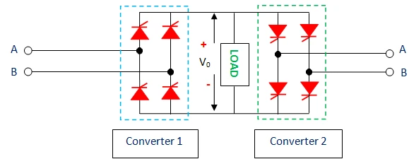
What is a single-phase dual converter?
A single-phase dual converter places two single-phase full-bridge controlled converters back-to-back across a common DC load. Converter 1 — the positive group (P) — carries positive load current, and converter 2 — the negative group (N) — carries negative load current. Because either converter can act as a rectifier or as a line-commutated inverter, the pair can source or sink both voltage and current, giving true four-quadrant operation. This is exactly what a reversible DC drive needs: forward and reverse motoring plus regenerative braking in both directions.
The α₁ + α₂ = 180° control law
For the two converters to present the same average voltage to the load without a large DC circulating current, they are fired so that their average outputs are equal and opposite:
Setting cos α₁ = −cos α₂ gives the fundamental dual-converter relationship α₁ + α₂ = 180°. The average load voltage is therefore:
This is positive for α₁ < 90° (converter 1 rectifies — quadrant I) and negative for α₁ > 90° (converter 1 inverts — quadrant IV). At α₁ = 90° the average output is zero.
Circulating-current vs circulating-free mode
| Aspect | Circulating-current mode | Circulating-free mode |
|---|---|---|
| Converters active | Both simultaneously (α₁ + α₂ = 180°) | Only one at a time |
| Reactor | Required, to limit circulating current | Not required |
| Response | Fast, smooth, no dead-band at current reversal | Short changeover delay at current reversal |
| Losses | Extra loss from circulating current | Lower losses |
In the circulating-current mode both bridges conduct together. Their averages cancel, but their instantaneous voltages differ; that difference appears across the current-limiting reactor and drives a current that circulates between the converters. Its peak value is:
Four-quadrant operation
With load current taken as positive, converter 1 alone visits quadrant I (+V, +I, forward motoring) for α₁ < 90° and quadrant IV (−V, +I, forward braking / regeneration) for α₁ > 90°. When the load current must reverse, converter 2 takes over and mirrors this into quadrants II and III — so a dual converter covers the entire V–I plane, which a single converter cannot.
The simulator does not read these formulas to draw the curves. It generates each full-bridge output from the real device conduction, forms the load voltage as v₀ = (v₁ − v₂)/2 and integrates the circulating current across the reactor, then measures the results and compares them to the equations above in the accuracy panel — they agree to better than 0.05%.
Advanced options in this simulator
- SCR model: add a forward drop
V_fand on-resistanceR_on; each bridge conducts through two SCRs, so the load-path drop is2·V_f + 2·R_on·i— it lowers the shown load voltage but not the circulating current, and the accuracy check stays locked to the ideal(2Vm/π)cos α₁envelope. - Transformer: a turns ratio scales the peak voltage
Vmapplied to both bridges. - Filter & protection: a series-L, shunt-C or LC output filter, an optional RC snubber, and a live protection-margin check of the SCR PIV (= Vm) and average current against the ratings you enter.
- Harmonic spectrum analysis: a real FFT of the load voltage or current with the ripple / THD figure (relative to |DC|, so it works in the inversion quadrant too).
- Export & capture: download the full waveform data as CSV, a text report, or a PNG screenshot of the scope.
Adding an output filter (L, C or LC)
The dual converter's load voltage still carries ripple at multiples of the supply frequency. An output filter smooths it: a series inductor (choke) smooths the load current with almost no change in average voltage; a shunt capacitor holds the voltage up and cuts ripple sharply; and an LC filter combines both for strong ripple attenuation. This simulator integrates the real filter differential equations — no approximate factors — so the Load ripple reading and the smoothed v₀ trace are physically exact. The four-quadrant average Vo = (2Vm/π)cos α₁ is unchanged by a choke and shifts only when a capacitor peak-charges the output.
Frequently asked questions
Why must α₁ + α₂ = 180° in a dual converter?
So that the two converters present equal and opposite average voltages to the load. With Vdc1 = (2Vm/π)cos α₁ and Vdc2 = (2Vm/π)cos α₂, the condition Vdc1 = −Vdc2 forces cos α₁ = −cos α₂, i.e. α₁ + α₂ = 180°. This keeps the DC circulating current at zero.
What limits the circulating current?
A current-limiting reactor (inductor) placed between the two converters. The instantaneous voltage difference between the bridges appears across this reactor; the smaller the reactor, the larger the circulating current. Its peak is (2Vm/ωLr)(1 − cos α₁) — reduce it by increasing Lr.
How does a dual converter give four-quadrant operation?
Converter 1 handles positive load current (quadrants I and IV depending on voltage polarity) and converter 2 handles negative load current (quadrants II and III). Together they can apply either voltage polarity with either current direction, which is what reversible drives with regenerative braking require.
When is converter 1 a rectifier and when is it an inverter?
For α₁ < 90° the average output voltage is positive and converter 1 acts as a rectifier (power flows AC→DC, motoring). For α₁ > 90° the average voltage is negative and it acts as a line-commutated inverter (power flows DC→AC, regenerative braking).
Do both modes give the same average output voltage?
Yes. Whether you use circulating-current or circulating-free control, the average load voltage is Vo = (2Vm/π)cos α₁. The modes differ in the circulating current, the need for a reactor, and the behaviour at current reversal.
What does the harmonic spectrum show?
An FFT of the load voltage (or current), expressed relative to the |DC| level so it works in the inversion quadrant too. The firing angle α₁ sets both the DC level and the harmonic content. Switch between the voltage and current spectra and choose how many harmonics to display.