What is a single-phase voltage-source inverter (VSI)?
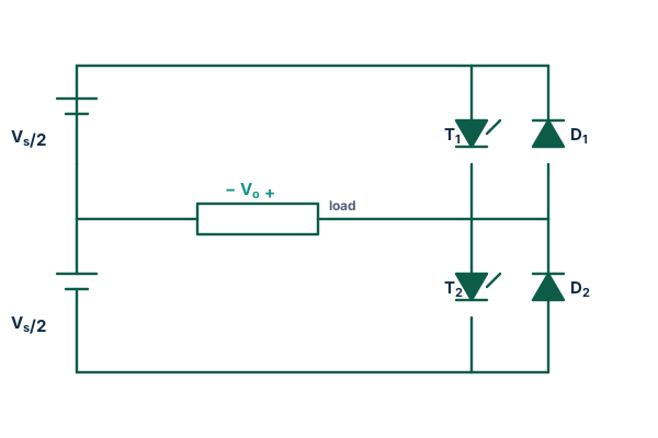
A voltage-source inverter (VSI) is fed from a stiff DC voltage — held constant by a large capacitor — and switches that voltage onto the load to synthesise AC. In the single-phase half-bridge the DC bus is split into two Vs/2 halves with a centre tap. Turning on the upper switch T1 connects the load to +Vs/2; turning on the lower switch T2 connects it to −Vs/2. The two anti-parallel diodes D1/D2 carry the load current whenever it opposes the applied voltage (inductive loads).
Output voltage, fundamental and RMS
For square-wave operation the output alternates between ±Vdc/2 every half-cycle:
This simulator forces the exact switching voltage and integrates the load L·di/dt = v − R·i, so every waveform, RMS and THD is exact.
Modulation depth & overmodulation (topic-specific)
With sinusoidal PWM a sine reference of relative amplitude ma is compared with a triangular carrier of ratio mf. In the linear region (ma ≤ 1) the fundamental is Vo1 = ma·Vdc/2, so the peak reaches at most Vdc/2 — only 78.5% of the square-wave ceiling 2Vdc/π. Increasing ma beyond 1 enters overmodulation, where the fundamental rises non-linearly and low-order harmonics reappear, until at ma ≈ 3.24 the output collapses into a pure square wave at the ceiling. The analyzer above shows exactly where you are on this curve.
VSI vs CSI, and half-bridge vs full-bridge
| Feature | Half-bridge VSI | Full-bridge VSI |
|---|---|---|
| Switches | 2 (+split bus) | 4 |
| Output swing | ±Vdc/2 | ±Vdc |
| Fundamental (square) | 2Vdc/π | 4Vdc/π |
| Bus | Needs split capacitors | Single bus |
Compare with the single-phase half-bridge and full-bridge inverter pages, the three-phase VSI, and the current-source dual, the single-phase CSI.
Applications
UPS systems, solar micro-inverters, induction heating, small motor drives and as the building block of the full-bridge and three-phase inverters.
Frequently asked questions
What is a single-phase VSI?
A voltage-source inverter fed from a stiff DC voltage; the half-bridge switches a split DC bus onto the load to make a square (or PWM) voltage of amplitude ±Vdc/2.
What is the output voltage?
Square-wave: fundamental peak 2Vdc/π, RMS √2·Vdc/π, total RMS Vdc/2, THD ≈ 48.3%. SPWM linear: Vo1 = ma·Vdc/2.
What is overmodulation?
Driving ma above 1 so the fundamental rises beyond the linear limit toward the square-wave ceiling 2Vdc/π, at the cost of reintroducing low-order harmonics.
How is a VSI different from a CSI?
The VSI has a stiff DC voltage (capacitor) and makes a square-wave voltage with anti-parallel diodes; the CSI has a stiff DC current (inductor) and makes a square-wave current with reverse-blocking devices.