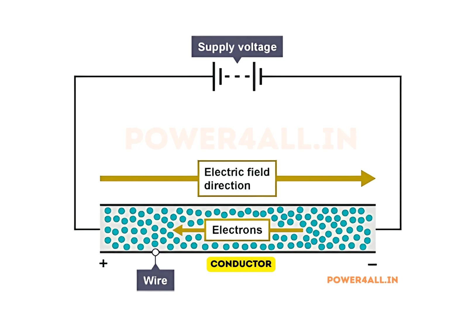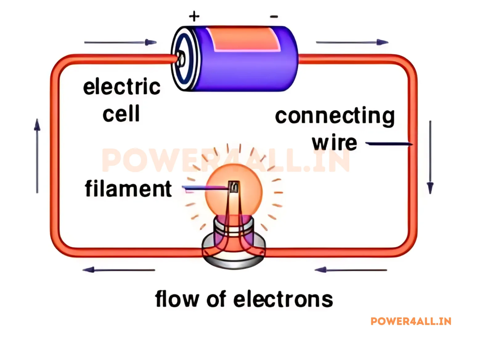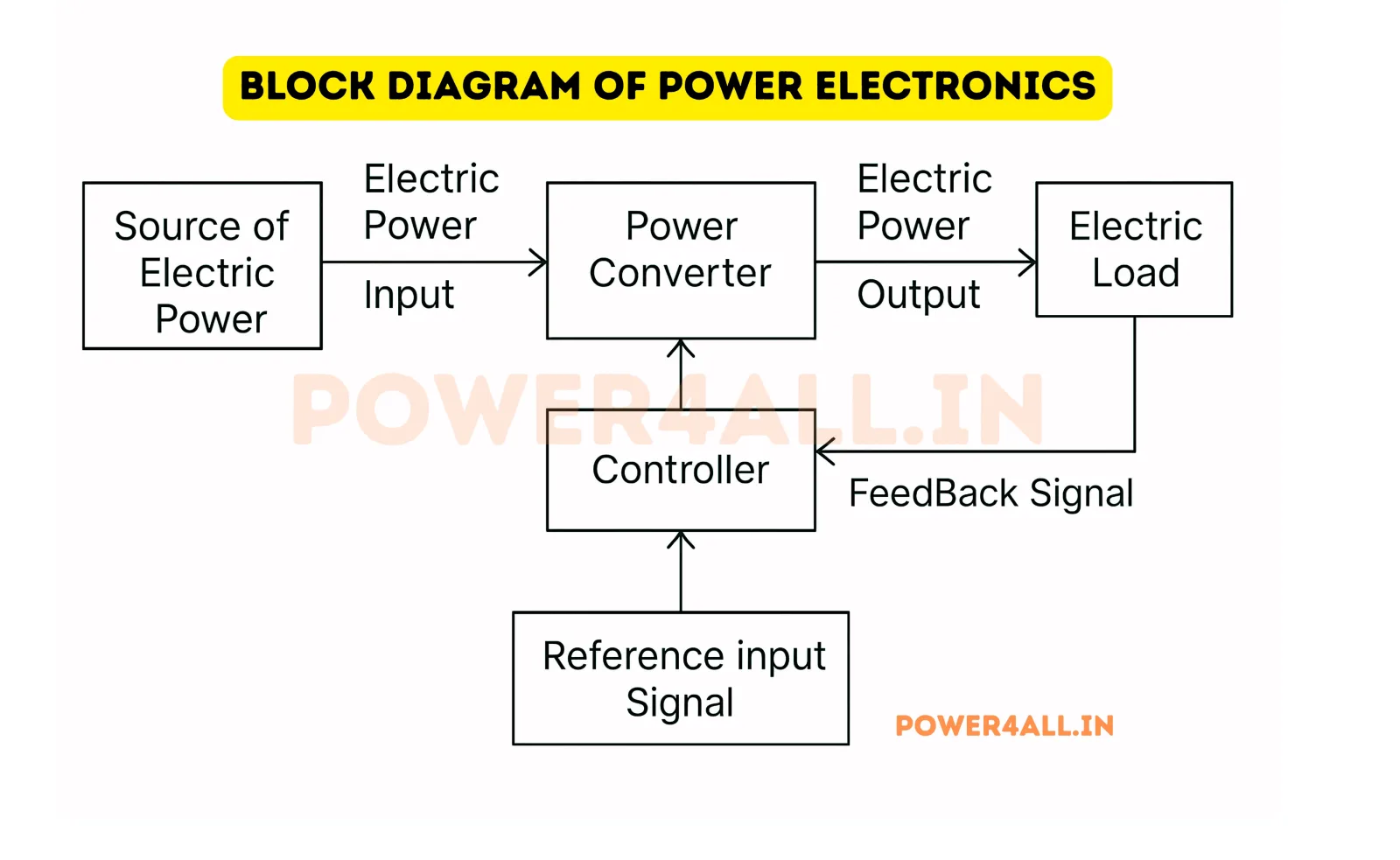
What is Power Electronics?
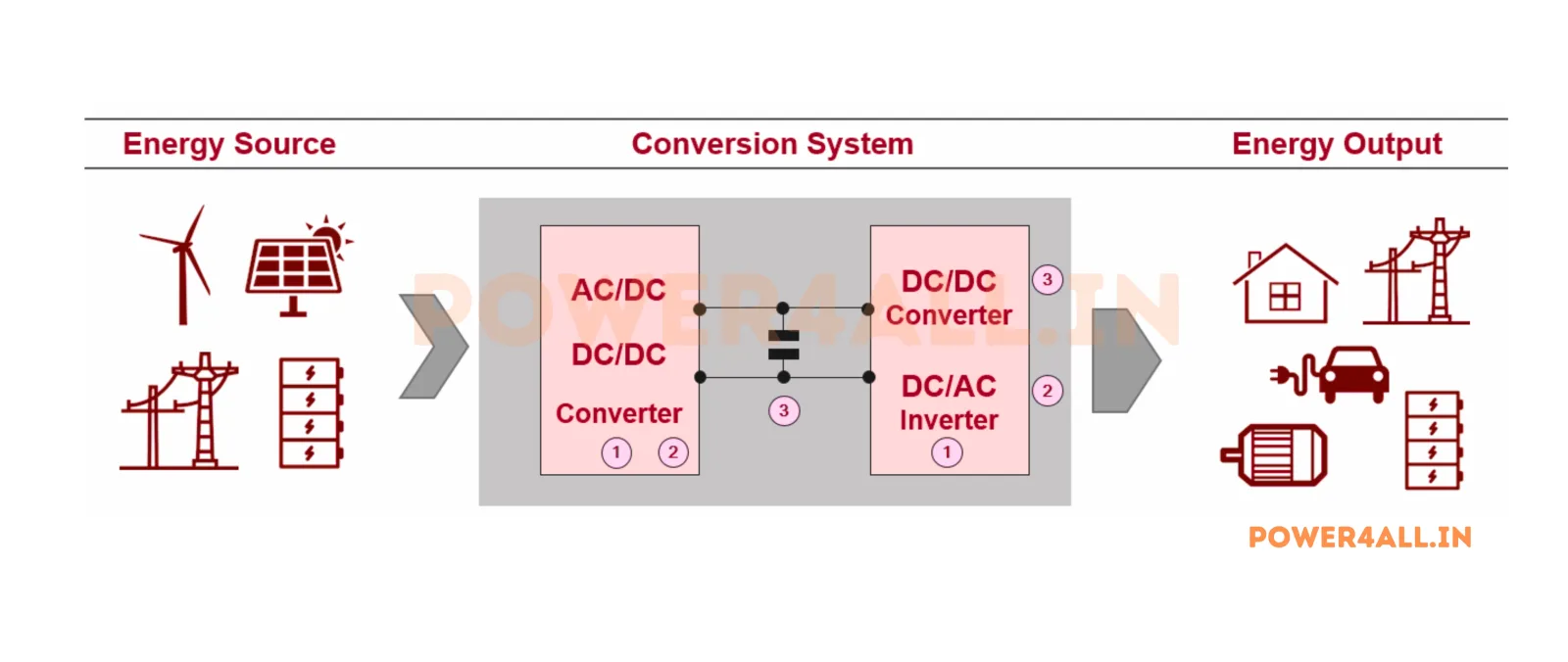
Comprehensive introduction to power electronics fundamentals and applications.
- Basic principles and concepts
- Applications in modern technology
- Key components and systems
Power4All · Learn
A complete, structured library — from basic electrical quantities and circuit laws through passive, magnetic and semiconductor components all the way to microcontrollers. Diagrams, formulas and worked examples for every topic.
Electrical quantities, circuit basics, AC/DC, waveforms and signals.
Comprehensive introduction to power electronics fundamentals and applications.
Understanding voltage, its measurement, and role in electrical circuits.
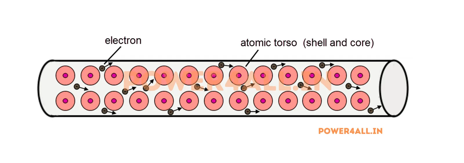
Explore electric current, its types, and measurement in electrical systems.
Understand electric charge, Coulomb's law, and how charge underpins voltage and current.
Explore electric power, watts, the P = VI relationship, AC/DC power and power factor.
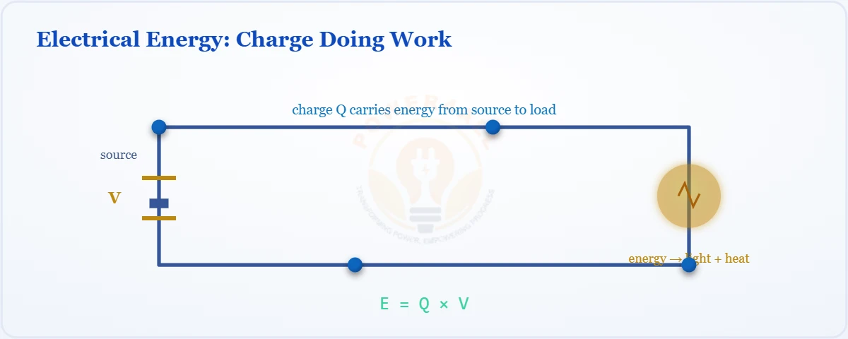
Learn electrical energy, the joule and kilowatt-hour, and how E = P × t drives your electricity bill.
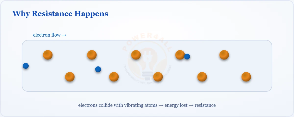
Understand electrical resistance, the ohm, and what controls how strongly a material opposes current.
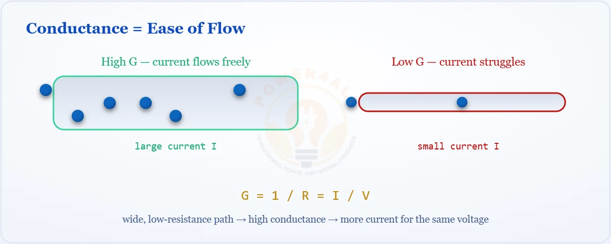
Explore conductance (G = 1/R), the siemens, and how easily a material allows current to flow.
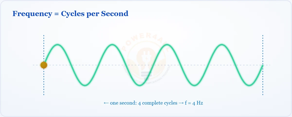
Understand frequency, the hertz, period (T = 1/f), and its role in AC systems and signals.
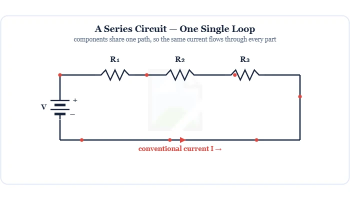
Components on one single path — the same current flows through every part, the supply voltage divides across them (V = V1+V2+V3), and resistances add up. Covers KVL, Ohm's law, the voltage divider & series vs parallel.
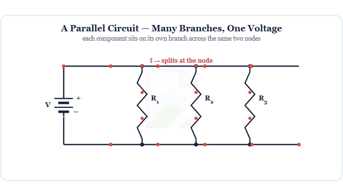
Components on separate branches across the same two nodes — the same voltage across each (V = V1 = V2), the current divides (I = I1+I2+I3), and total resistance is less than the smallest. Covers KCL, the current divider & why homes are wired this way.
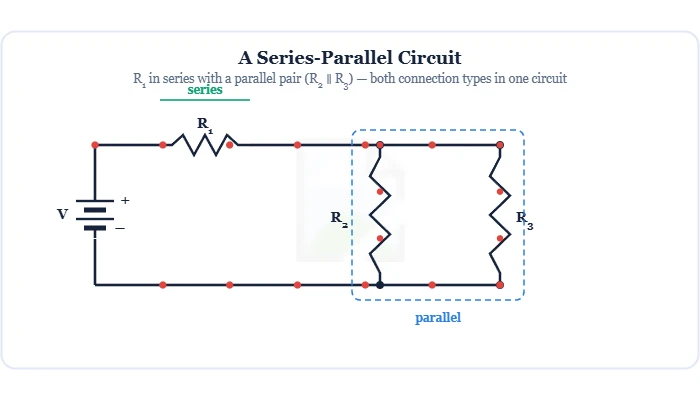
Combined networks that mix series and parallel connections. Learn to spot the groups and solve them by step-by-step reduction (combine parallel first, then series), with worked examples, ladder networks and the loaded voltage divider.
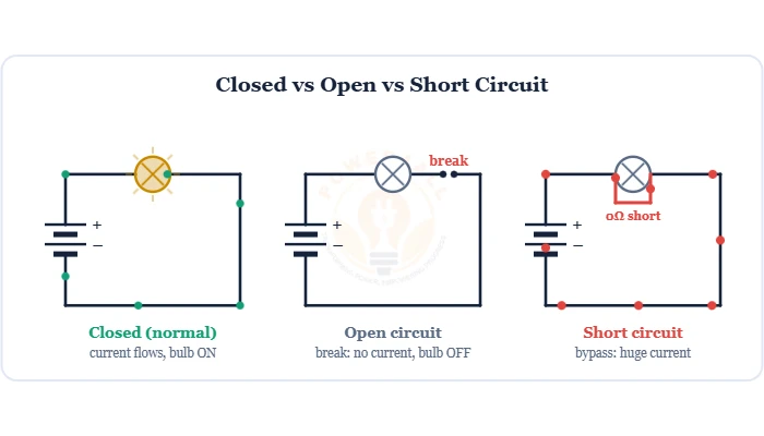
The two opposite circuit faults — an open circuit is a break (infinite R, no current), a short circuit is a zero-Ω bypass (huge current). Difference, causes, dangers & protection.
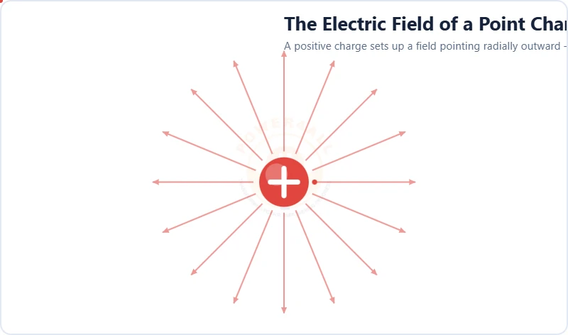
The invisible region of force around every charge. Learn the definition E = F/q, field lines and direction, the dipole, point-charge strength E = kQ/r² and the uniform field between capacitor plates E = V/d.
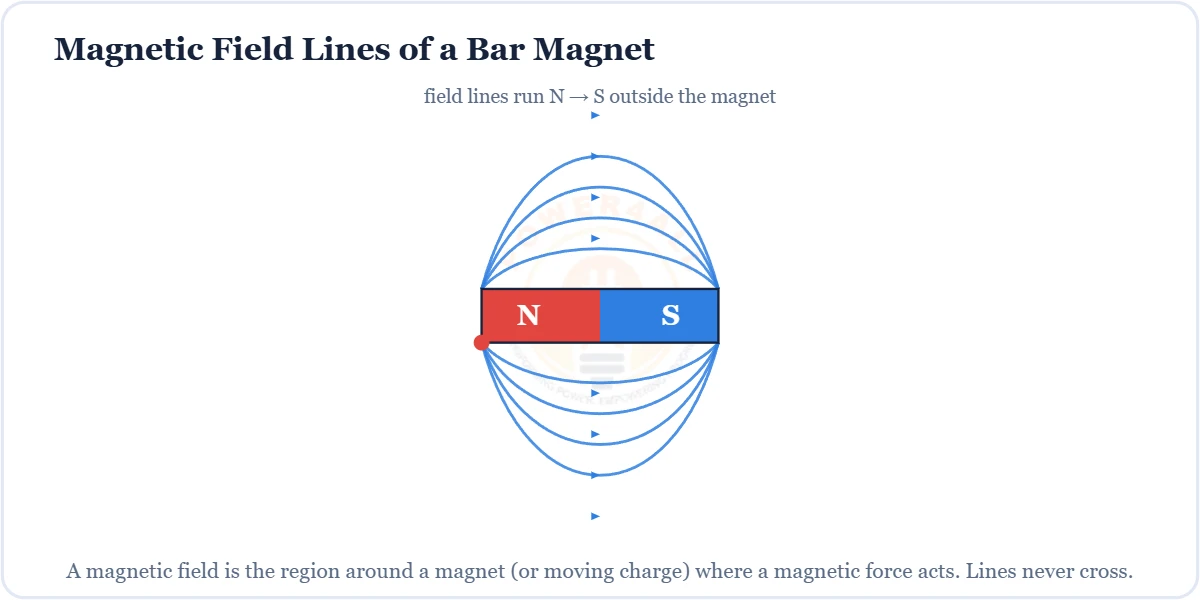
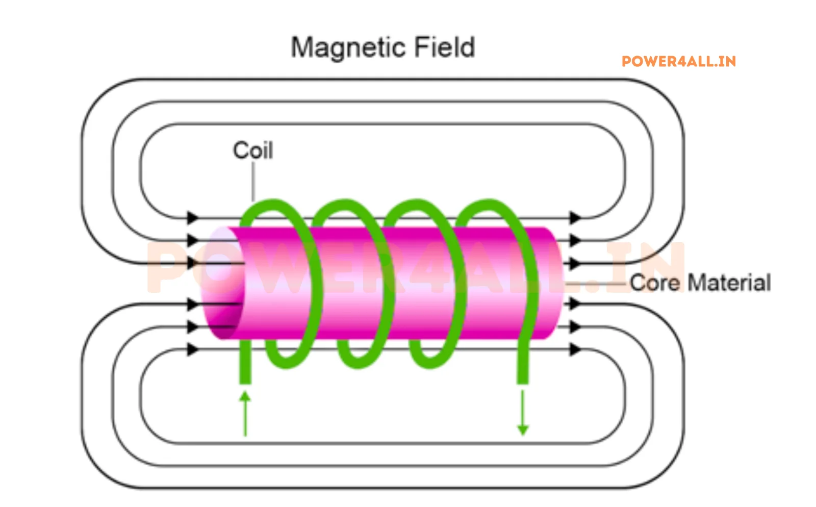
The region around a magnet or current where a magnetic force acts — field lines, the right-hand rule, flux density B = Φ/A, force F = BIL and the B–H curve.
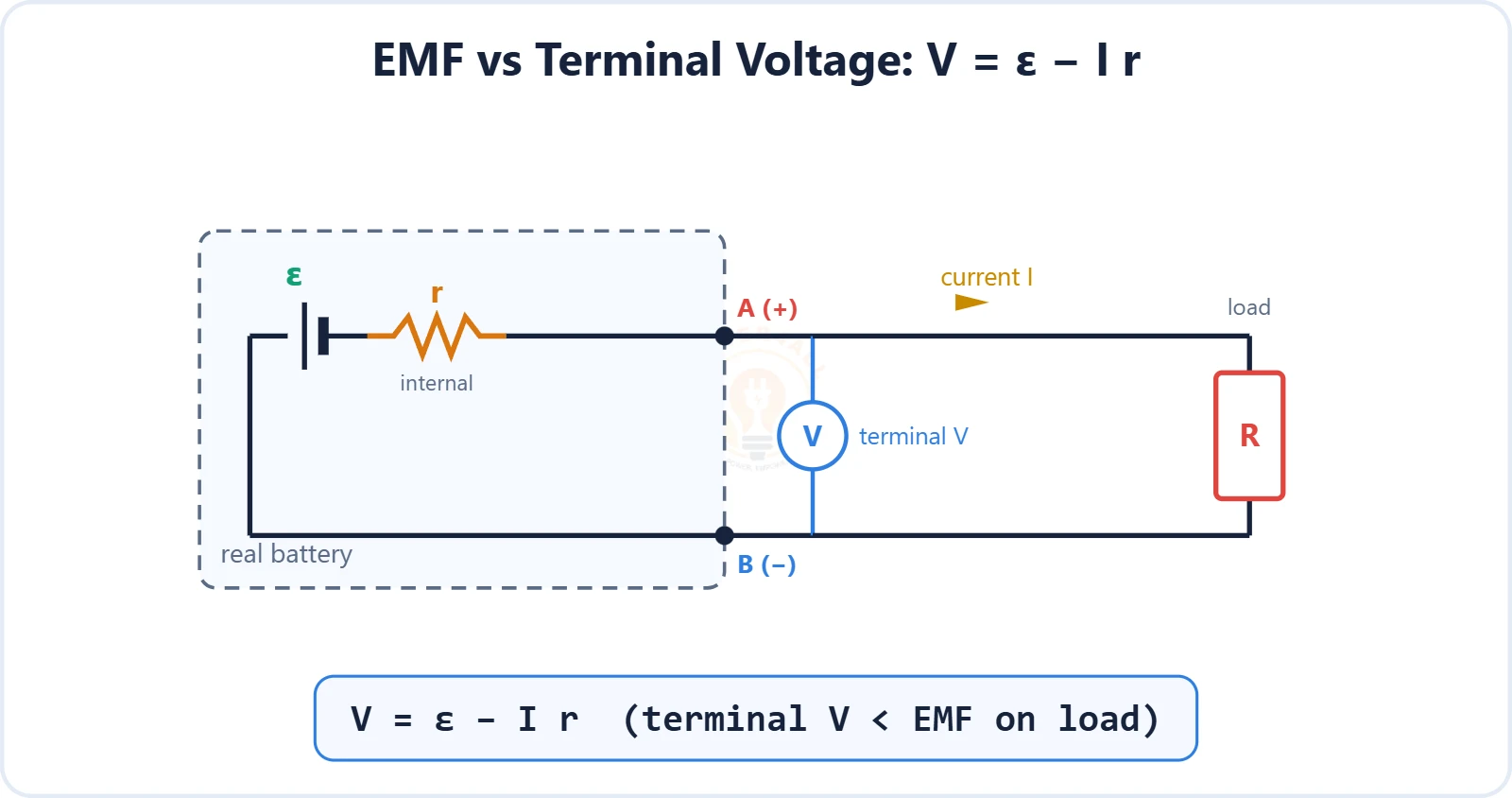
The driving energy a source gives per unit charge — EMF ε = W/Q, why it isn't really a force, EMF vs terminal voltage with internal resistance (V = ε − Ir), sources of EMF and cells in series & parallel.
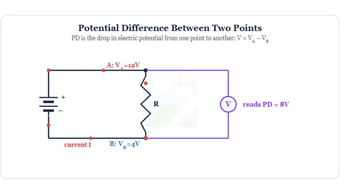
The difference in electric potential between two points — the energy per charge (V = W/Q) that drives current. Covers the volt, electric potential & reference, PD vs EMF and terminal voltage (V = ε − Ir), and measuring PD with a voltmeter.
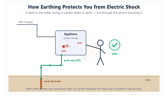
The safety connection to earth that prevents electric shock — grounding vs earthing, the earth-fault loop, types of earthing (plate/pipe/rod), TN/TT/IT systems, earth resistance & the earth pit.
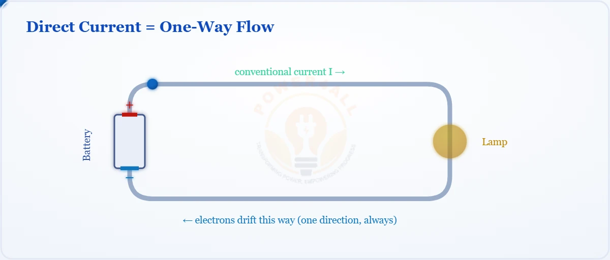
One-directional current explained — DC vs AC, sources, rectification, pure vs pulsating DC, formulas and uses.
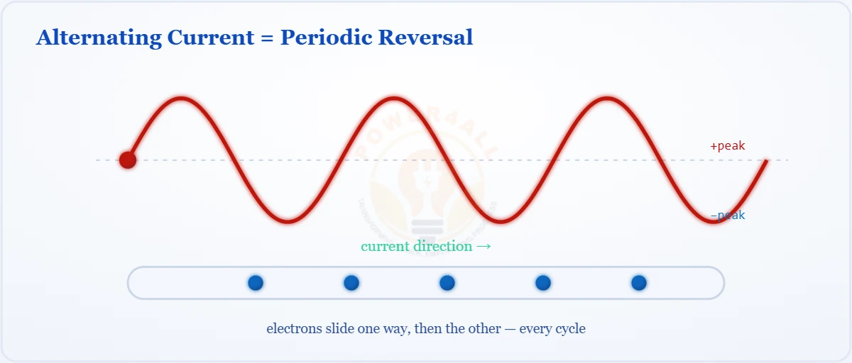
The sine-wave current that reverses direction — AC vs DC, generation, peak & RMS, frequency, phases and uses.
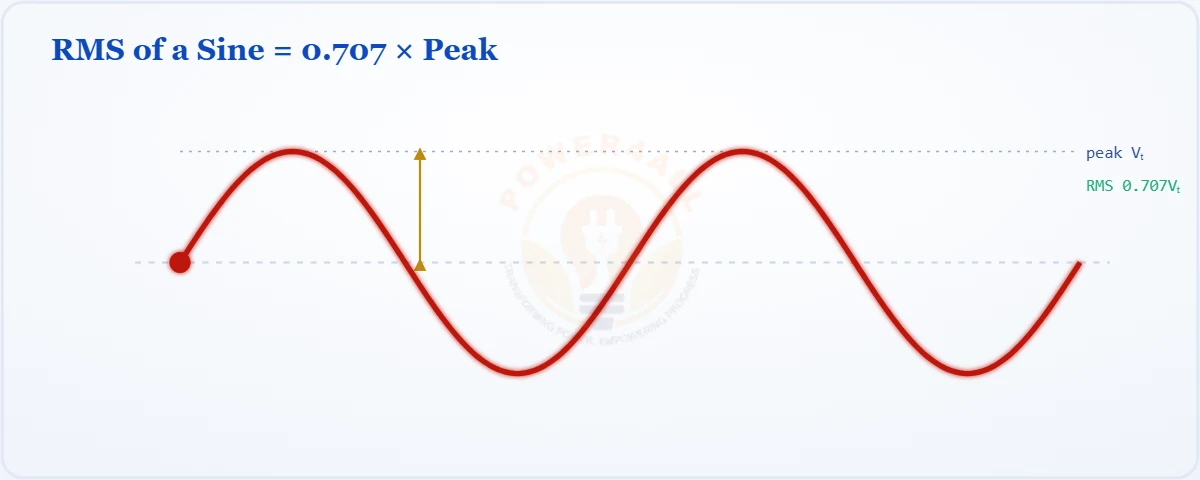
Root mean square — the effective value of AC. Why Vrms = 0.707 × peak, the square–mean–root process, and other waveforms.
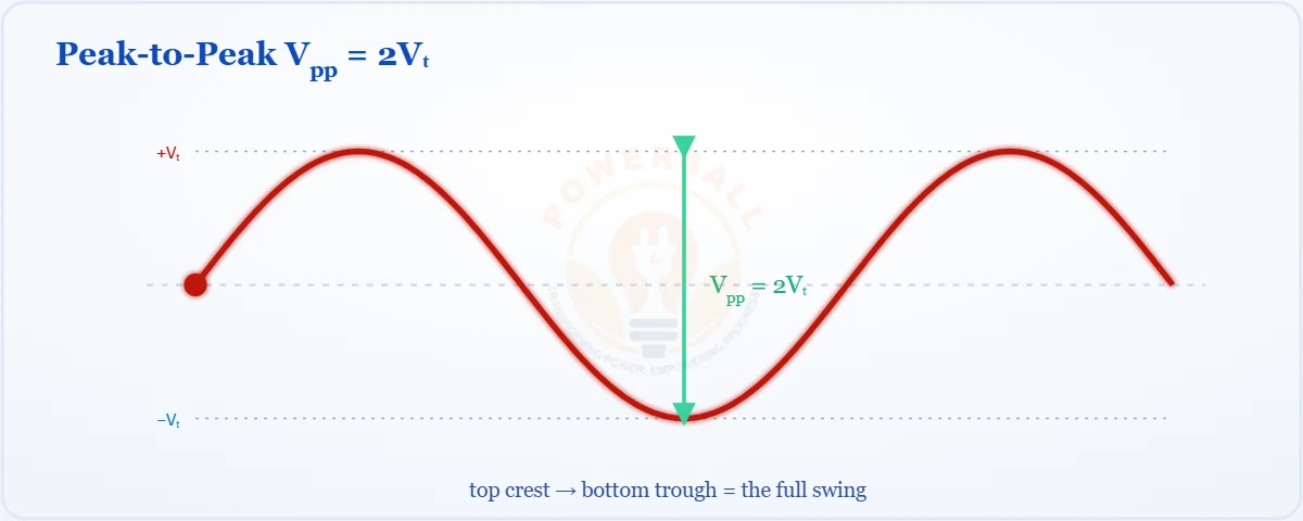
The peak value (amplitude, Vm) and peak-to-peak (Vpp = 2Vm) — how they relate to RMS, waveform values and ratings.
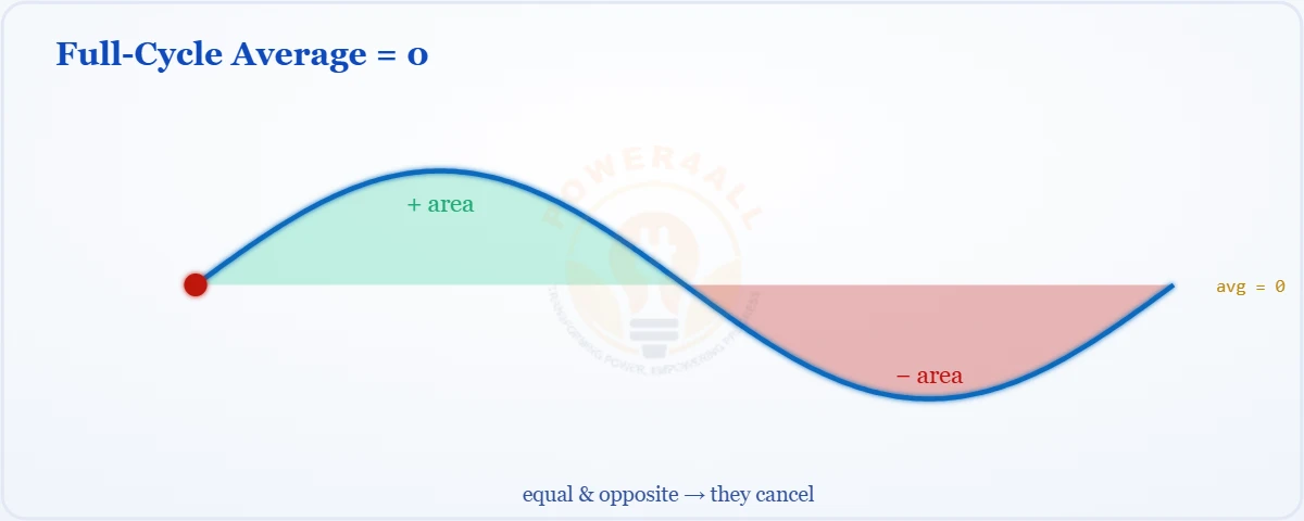
The mean of a waveform — why the full cycle is zero, the half-cycle average Vavg = 0.637 Vm, and average vs RMS.
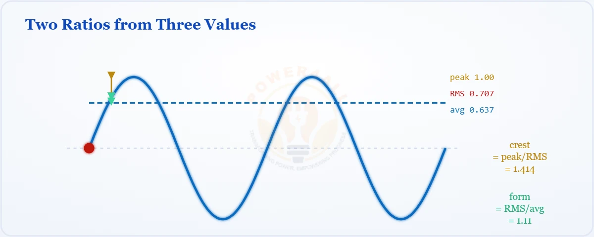
The two shape ratios of a waveform — form factor (RMS/avg = 1.11) and crest factor (peak/RMS = 1.414), with waveform values and uses.
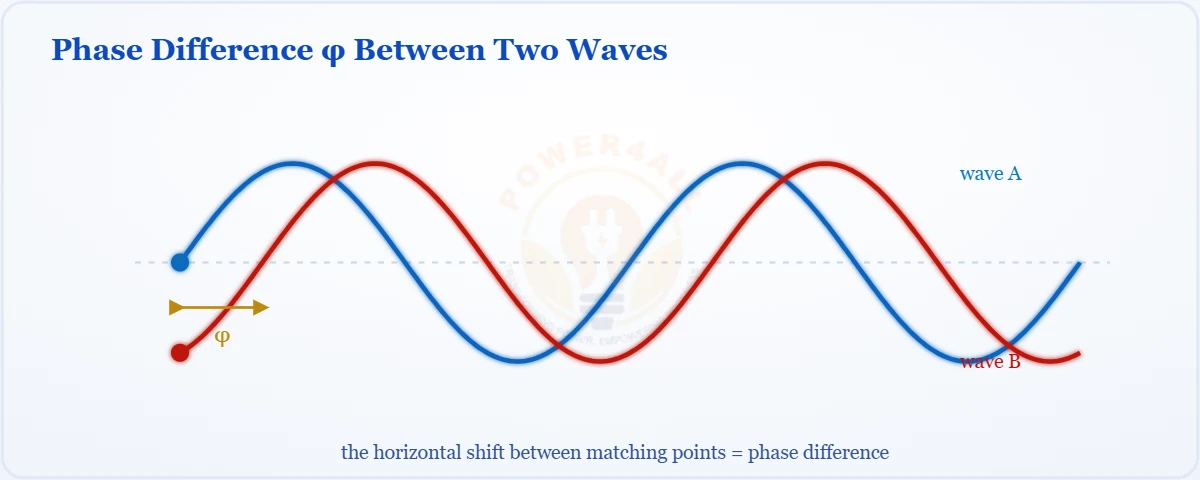
The phase angle φ and the offset between two waves — in-phase, quadrature, anti-phase, leading vs lagging and phase in R, L, C.
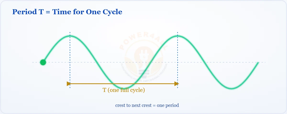
The period T (time for one cycle) and frequency f (cycles per second), the reciprocal T = 1/f, units and mains examples.
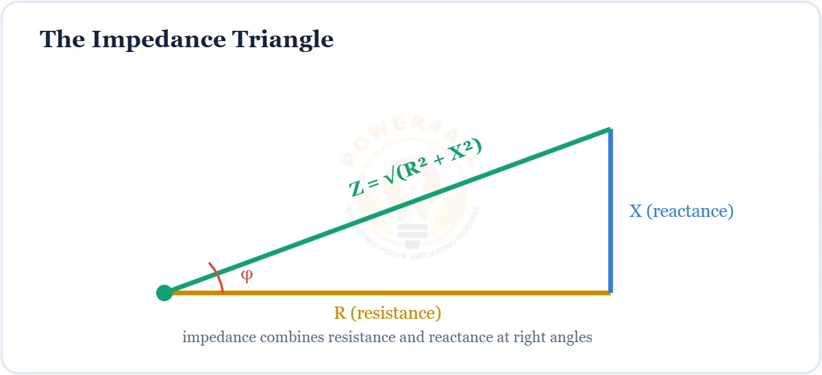
Total AC opposition — Z = R + jX, the impedance triangle, R/L/C impedance, frequency response and Ohm's law for AC.
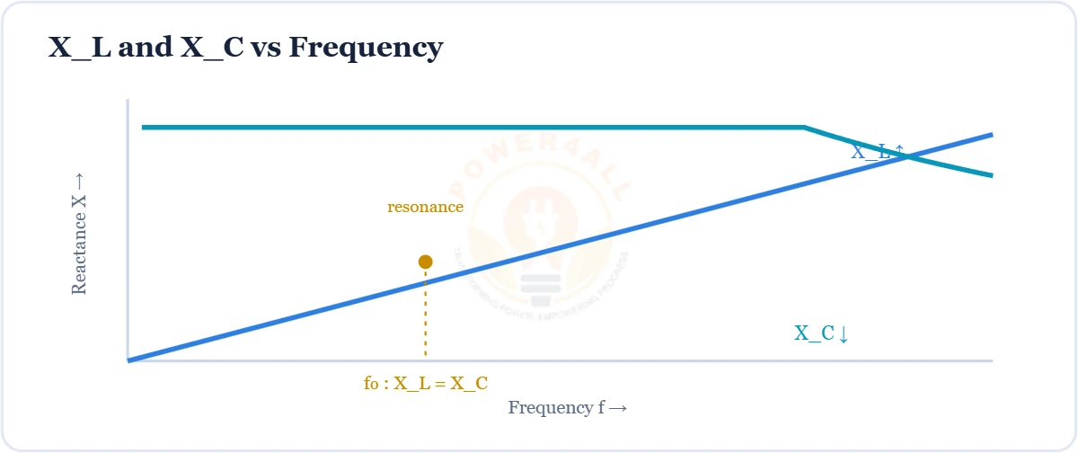
The AC opposition of inductors & capacitors — XL = 2πfL rises with frequency, XC = 1/2πfC falls, plus phase and resonance.
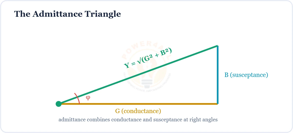
The ease of AC flow — Y = 1/Z, Y = G + jB, conductance & susceptance, and why admittances add in parallel circuits.
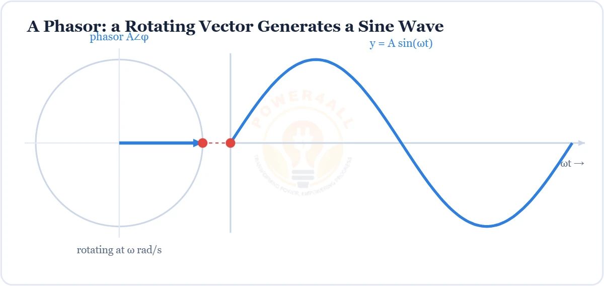
The rotating-vector tool that makes AC analysis easy — the j operator, rectangular a + jb & polar r∠θ forms, phasor arithmetic and circuit diagrams.
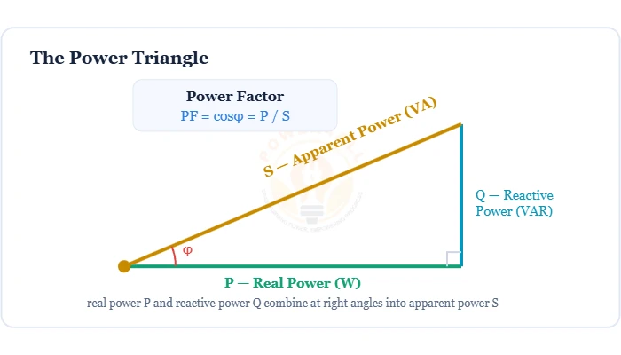
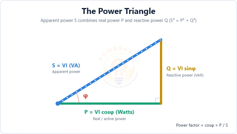
How much supplied power does useful work — PF = cosφ = P/S, the power triangle, leading vs lagging PF, and correction with capacitors.
The three kinds of AC power and how they fit together — real power P = VI cosφ (W), reactive power Q = VI sinφ (VAR) and apparent power S = VI (VA), plus the power triangle and power factor.
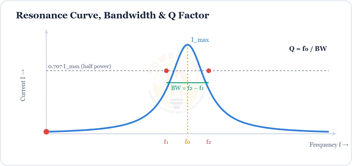
When XL = XC and reactances cancel — f0 = 1/2π√(LC), series (Z min) vs parallel tank (Z max), plus Q factor and bandwidth.
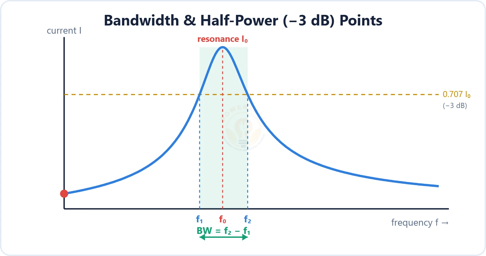
The sharpness of resonance — quality factor Q, bandwidth between the half-power (−3 dB) points, and the link Q = f₀/BW, with RLC formulas and the energy definition.
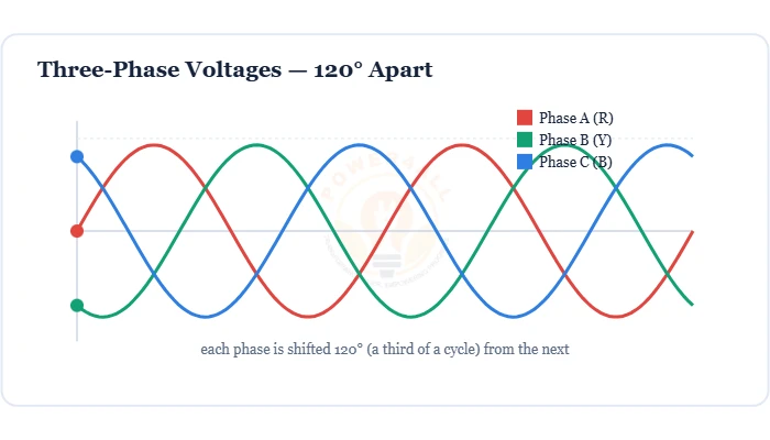
Three AC voltages 120° apart that power the grid — star vs delta, line vs phase (√3), three-phase power P = √3 VLILcosφ and why it beats single-phase.
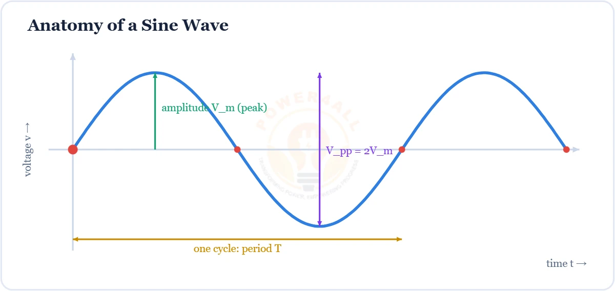
The pure, fundamental AC waveform — v(t) = Vm sin(2πft + φ), with amplitude, period, frequency, phase and peak / RMS / average values.
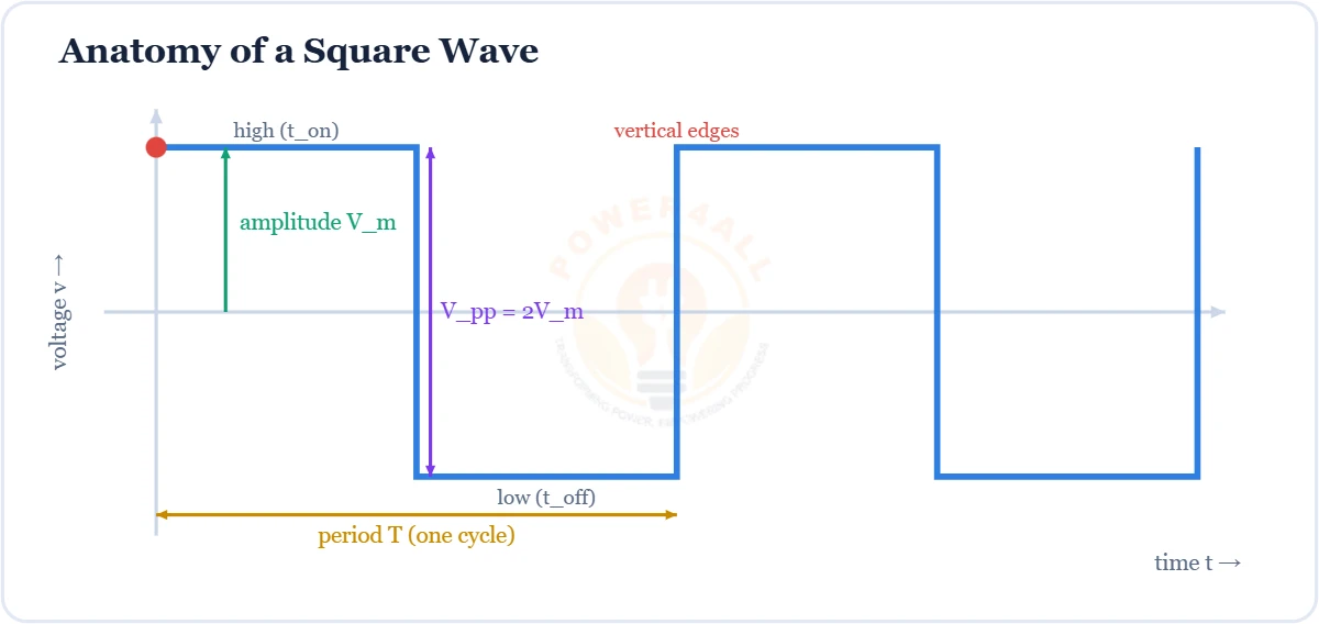
The two-level ON/OFF waveform of digital & switching circuits — duty cycle D = ton/T, odd-harmonic Fourier series, spectrum, RMS values and PWM.
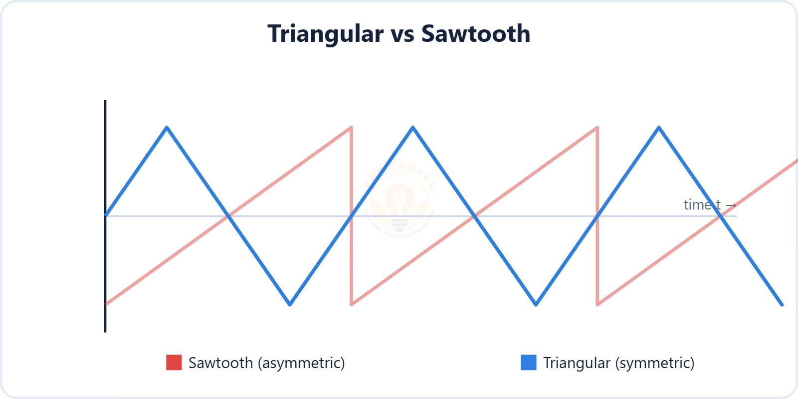
Ramp-based waveforms used in PWM generation, timing and signal processing.
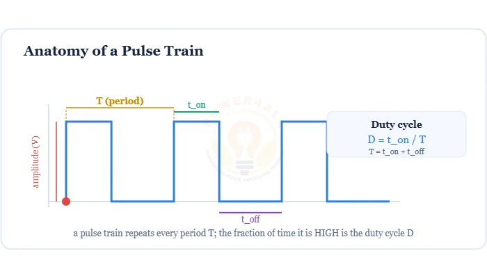
The on/off waveform that controls motors, LEDs & power supplies — pulse anatomy, duty cycle D = ton/T, average voltage Vavg = D×Vin and SPWM generation.
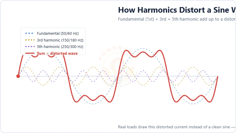
The extra frequencies that distort AC and how we measure them — harmonic order, odd/even/triplen harmonics, the THD formula, the spectrum, nonlinear-load sources, effects and mitigation.
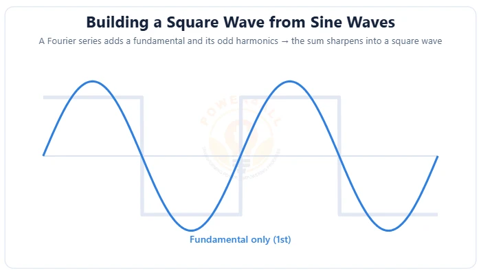
How any periodic waveform is a sum of sine waves — the Fourier series formula f(t) = a₀/2 + ∑(aₙcos nωt + bₙsin nωt), fundamental & harmonics, building a square wave, symmetry, the spectrum & the Gibbs phenomenon.
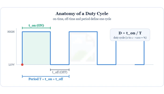
The fraction of each cycle a signal is ON — duty cycle D = ton/T (0–100%), how it sets the average voltage Vavg = D×V, complementary duty & dead-time, and PWM control of motors, LEDs & power supplies.
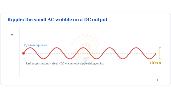
How much AC is left on a rectifier’s DC output, and the ripple factor that measures it.
Fundamental laws, network theorems and circuit-analysis methods.
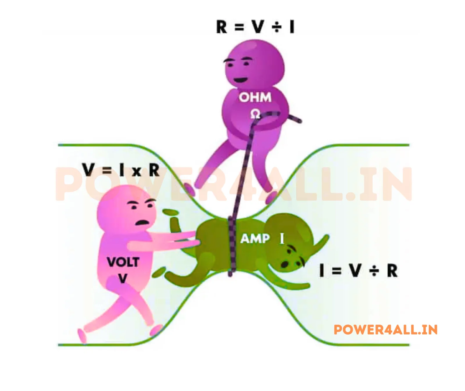
Fundamental relationship between voltage, current, and resistance.
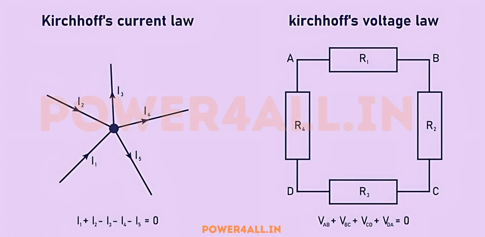
Current and voltage laws for analyzing electrical circuits.
Current and voltage laws for analyzing electrical circuits.
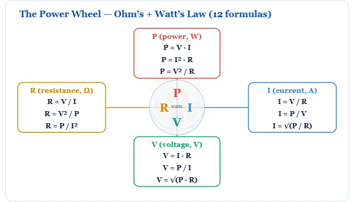
Power = voltage × current, its three forms, and the 12-formula power wheel.
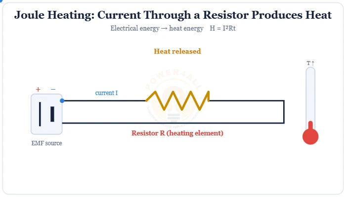
The heating effect of current: how much heat a resistance produces, H = I²Rt.
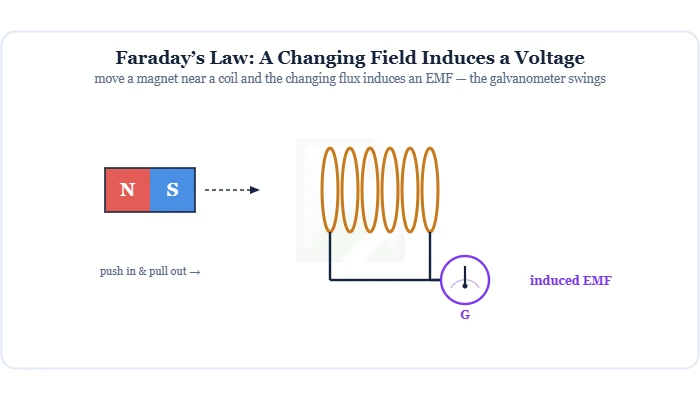
Electromagnetic induction — a changing magnetic flux induces a voltage: EMF = −N dΦ/dt. Covers magnetic flux (Φ = BA cosθ), Lenz's law & the minus sign, the three ways to induce an EMF, and the AC generator behind the grid.
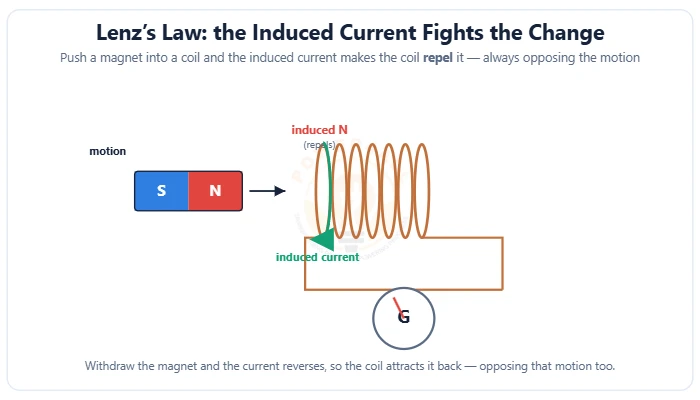
The direction rule of induction — the induced current always opposes the change in flux that creates it. The minus sign in EMF = −N dΦ/dt, finding the direction, the copper-tube demo, eddy currents & energy conservation.
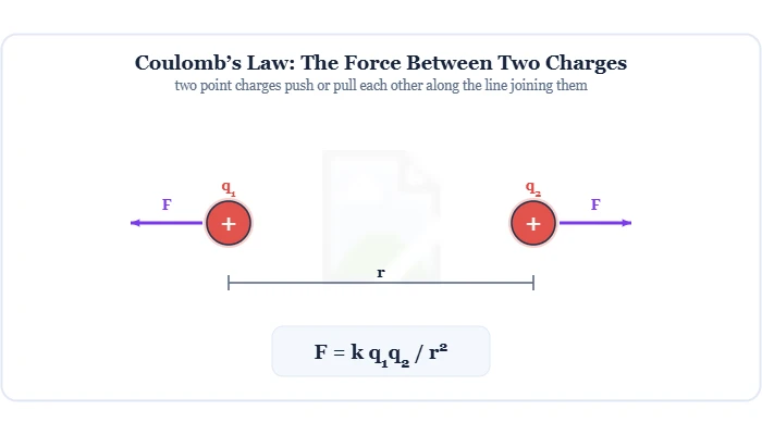
The electrostatic force between two charges: F = k q1q2/r2. Covers the Coulomb constant (8.99×10⁹), why like charges repel & unlike attract, the inverse-square law, superposition, and the link to the electric field.
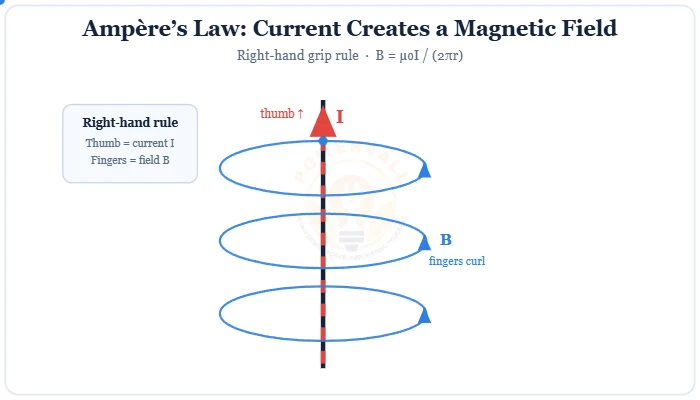
The magnetic effect of current: the field around a loop, ∮B·dl = µ₀I.
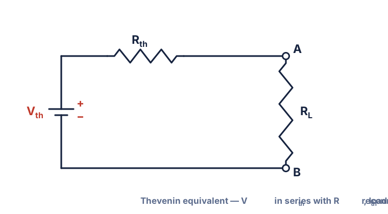
Reduce any linear network to a single voltage source in series with a resistance.
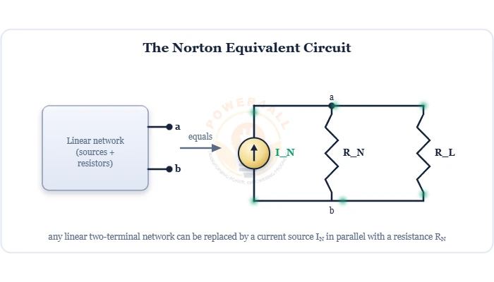
Replace any linear two-terminal network with a current source IN in parallel with a resistance RN — find IN & RN, source transformation with Thévenin, and load current.
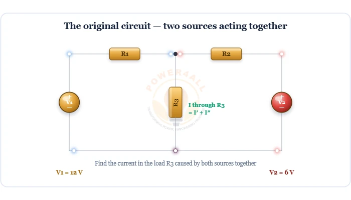
One source at a time: in a linear circuit the total current or voltage equals the sum of the effects of each independent source acting alone — turn voltage sources into shorts, current sources into opens, solve, then add.
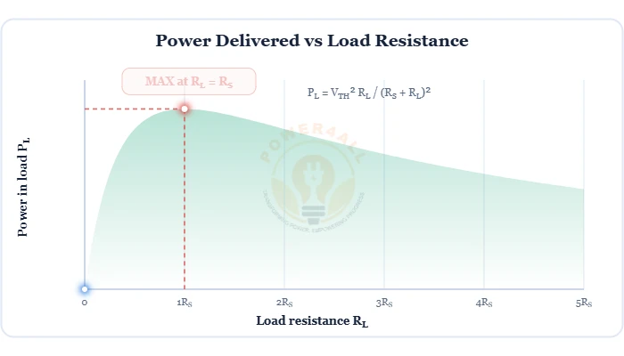
Maximum power reaches a load when RL = RS — the power curve, Pmax = VTH²/4RS, derivation, the 50% efficiency result and AC conjugate matching.
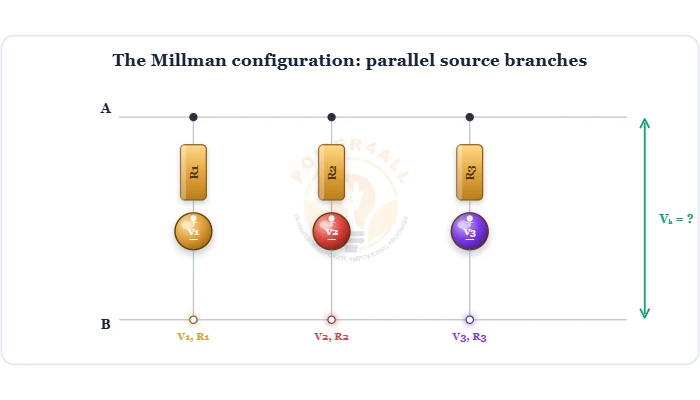
The fastest way to solve parallel source branches: the common terminal voltage is V = ΣVG / ΣG, where G = 1/R. Reduce many parallel batteries or supplies to one equivalent source (Veq, Req).
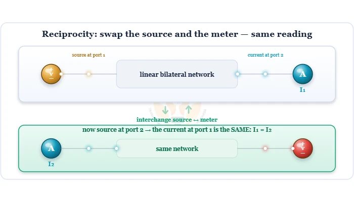
A symmetry of linear circuits: in a linear, bilateral, single-source network, swap the source and the meter and the current is unchanged. The transfer resistance V/I is the same both ways — the basis of antenna reciprocity.
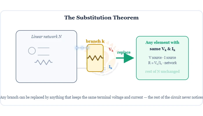
Replace any branch by anything with the same terminal voltage and current — a source or a resistor — and the rest of the circuit is unchanged. Statement, conditions, proof and worked examples.
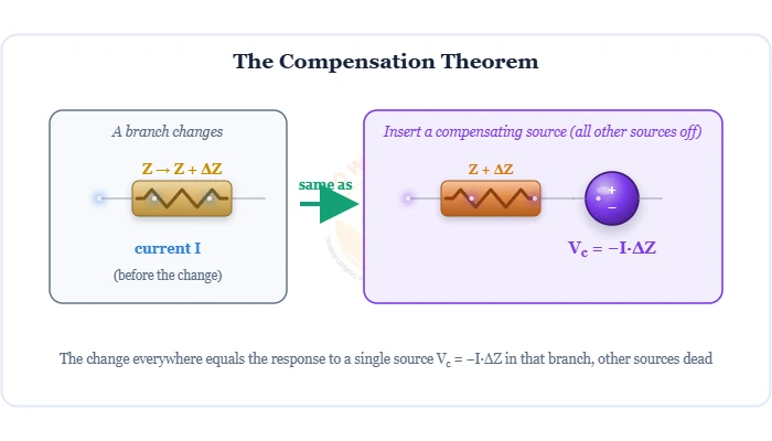
A branch impedance change ΔZ acts like a compensating source Vc = −I·ΔZ with all other sources off — find the effect without re-solving the circuit. Statement, formula, derivation and worked example.
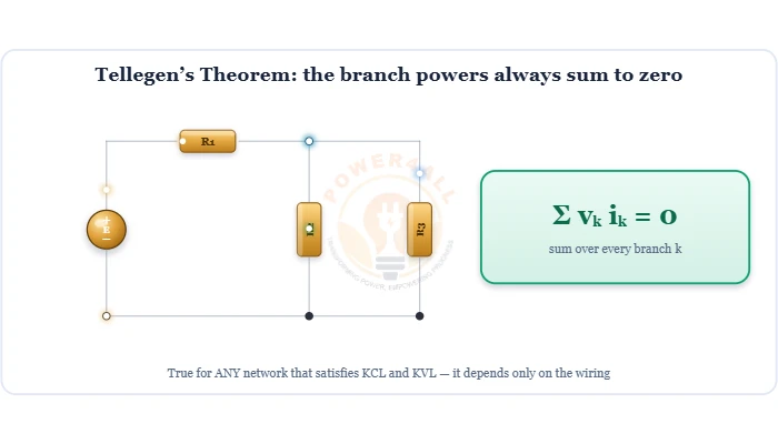
The most general power result in circuit theory: for any lumped network obeying KCL and KVL, the branch powers always sum to zero — Σ vk ik = 0. No linearity needed; it depends only on the wiring.
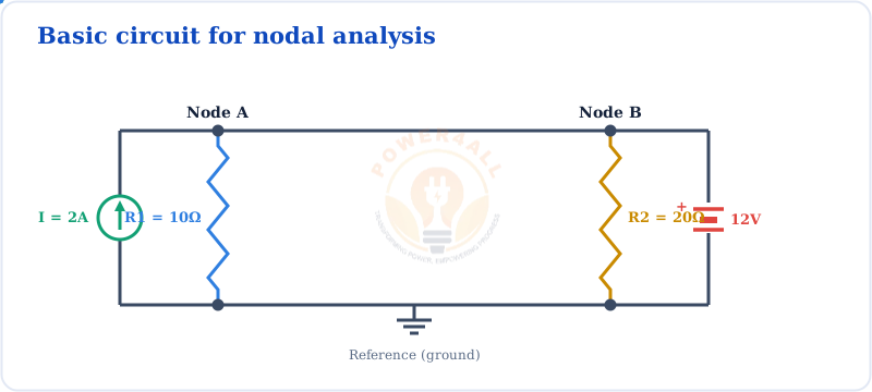
Solve circuits using node voltages and Kirchhoff's current law.
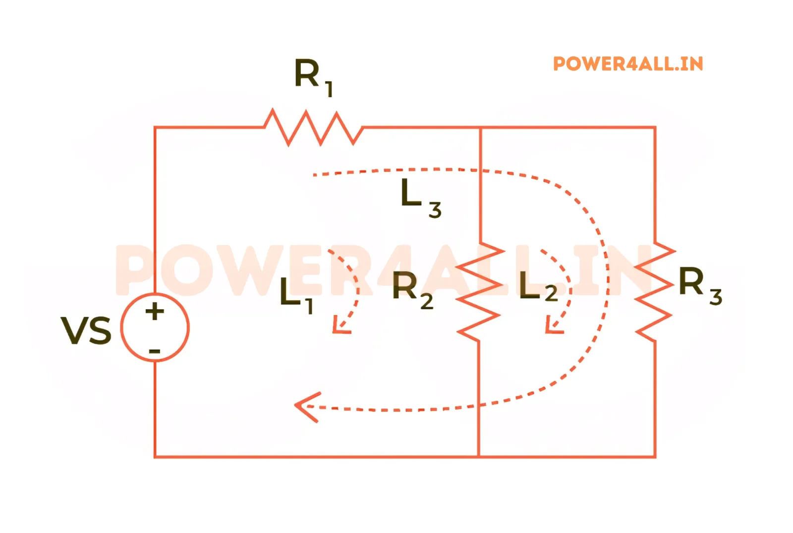
Solve circuits using loop currents and Kirchhoff's voltage law.
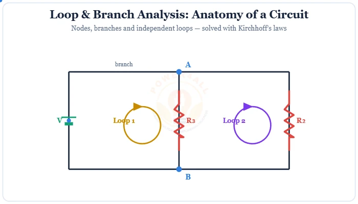
Solve any circuit with Kirchhoff's laws: the branch-current & loop-current methods.
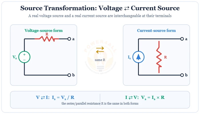
Swap a voltage source (series R) for a current source (parallel R): I = V/R, V = I×R.
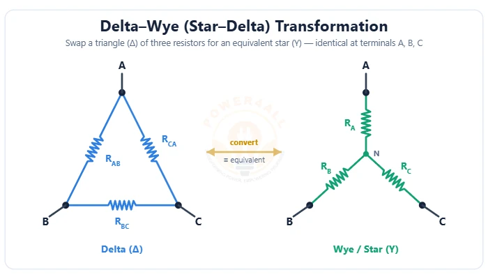
Swap a triangle (Δ) of resistors for an equivalent star (Y) — and back. The Δ→Y and Y→Δ formulas, the balanced case RΔ = 3RY, worked examples and cracking bridge circuits.
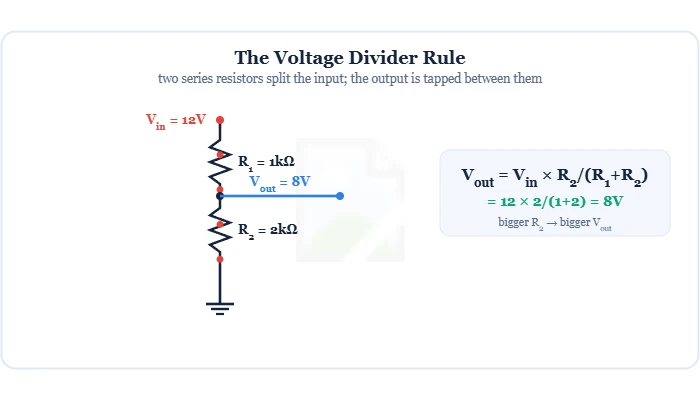
Two series resistors split a voltage: Vout = Vin·R2/(R1+R2). Covers the derivation, resistor ratios, multi-resistor taps, the loading effect, and the potentiometer as an adjustable divider.
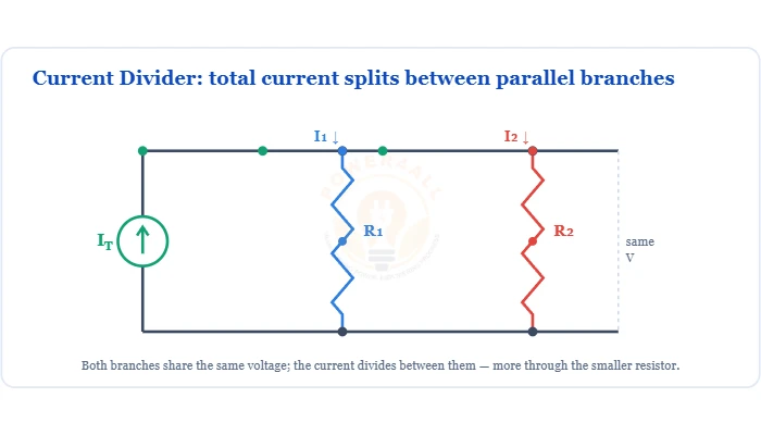
How current splits between parallel branches — the opposite-resistor formula and conductance form.
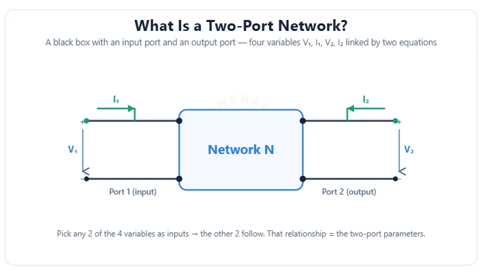
Model any circuit as a black box with an input & output port — four variables V1, I1, V2, I2. The Z, Y, h & ABCD parameters, their open/short-circuit tests, the transistor h-model & the cascade rule.
Resistors, capacitors, inductors, magnetics, transformers and EMI parts.
Basic passive components that oppose current flow and control voltage levels.
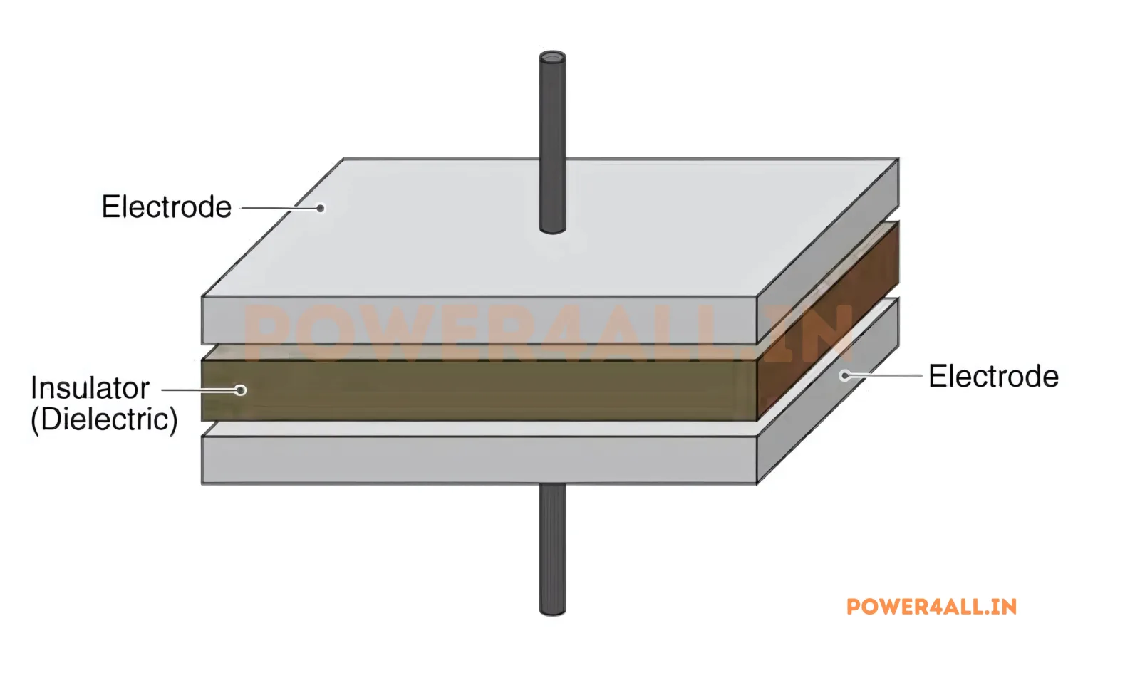
Energy storage device that stores electrical charge and opposes voltage changes.
Passive component that stores energy in magnetic field and opposes current changes.
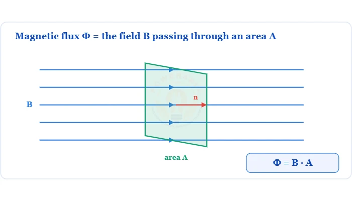
The total magnetic field through an area — Φ = B·A·cosθ, the weber, flux density and Faraday's law.
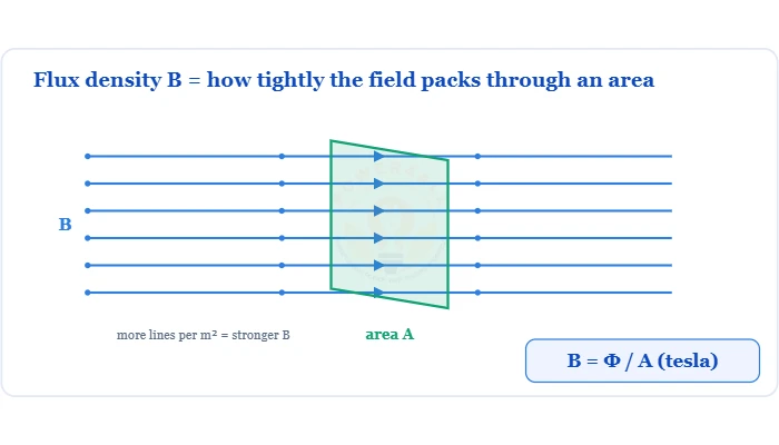
The magnetic field per unit area — B = Φ/A in tesla, permeability, the force F = BIL and typical values.
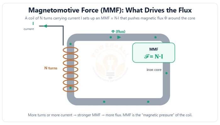
The magnetic “pressure” that drives flux around a circuit — MMF = N·I in ampere-turns. The EMF analogy (Φ = MMF/reluctance), field strength H = NI/l, and electromagnets.
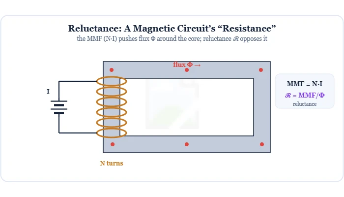
A magnetic circuit's resistance to flux: reluctance ℛ = ℓ/(μA), and its inverse, permeance. Covers the magnetic Ohm's law MMF = Φ×ℛ (Hopkinson), series & parallel reluctance, the air gap, and permeability.
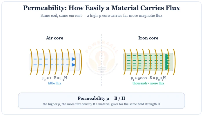
How easily a material carries magnetic flux: B = μH, μ = μ₀μr.
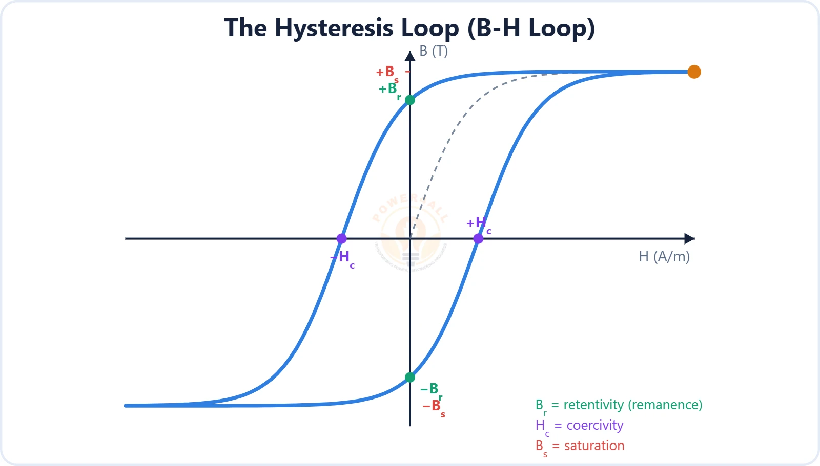
How magnetic materials magnetize: the B-H curve and hysteresis loop, saturation, retentivity (Br) & coercivity (Hc), permeability μ = B/H, hysteresis & core loss, and soft vs hard magnetic materials.
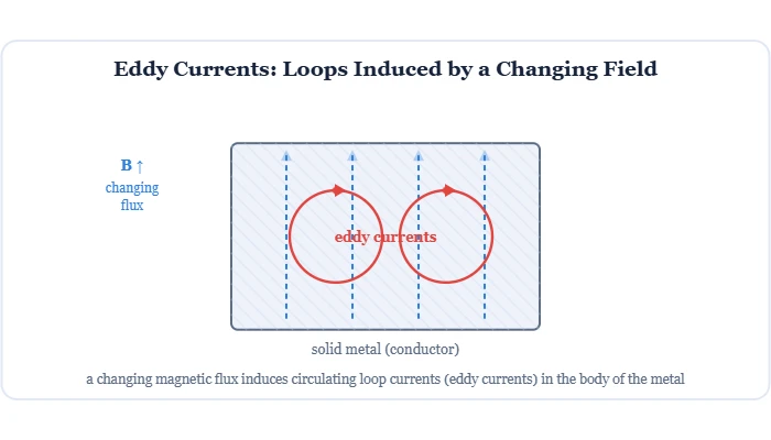
Circulating currents a changing magnetic flux induces in a conductor — Lenz's law, I²R heating & core losses, laminations, plus uses in induction heating, brakes & NDT.
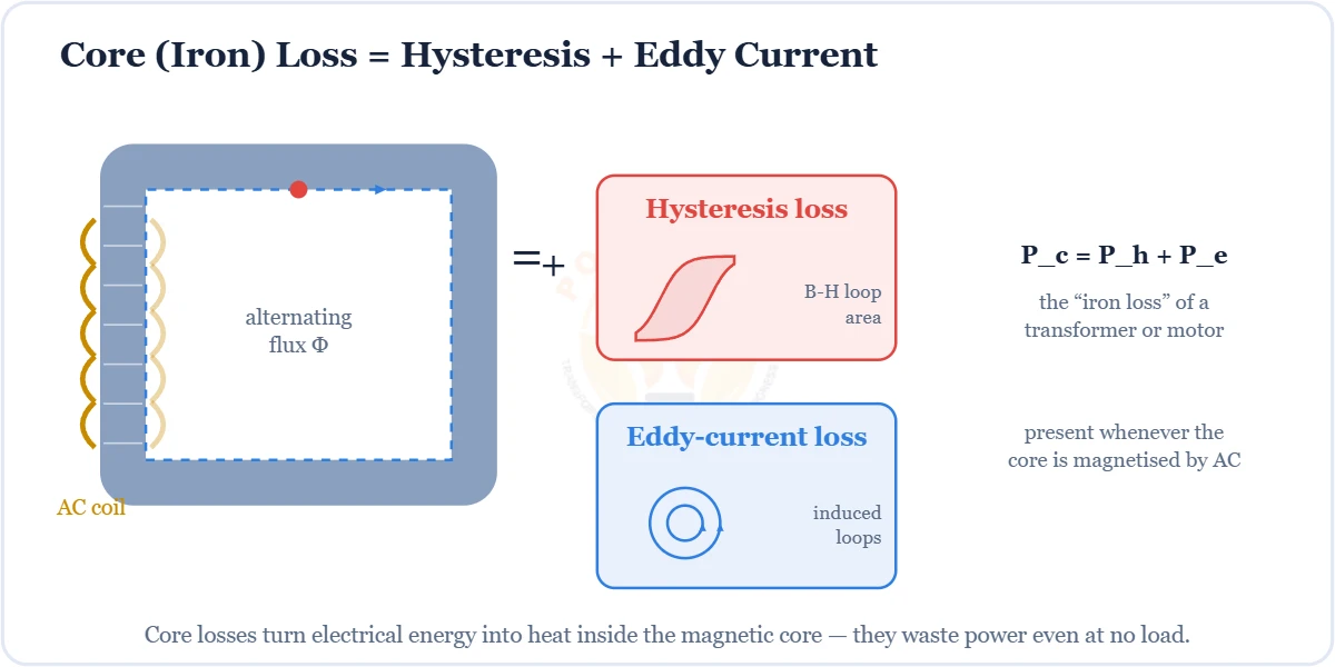
The heat wasted in a magnetic core under AC — hysteresis loss (B–H loop area) + eddy-current loss, the Steinmetz formula, lamination, and iron vs copper loss.
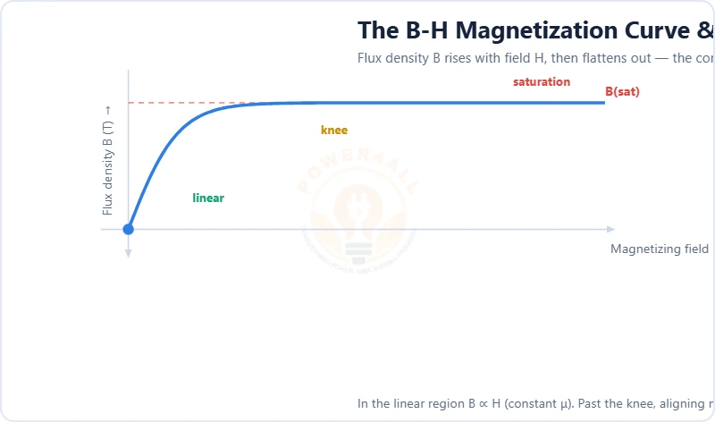
The flux ceiling of every magnetic core. Learn the B-H curve and knee, saturation flux density B(sat), magnetic domains, hysteresis, permeability collapse, and how core saturation causes inrush current and inductance drop.
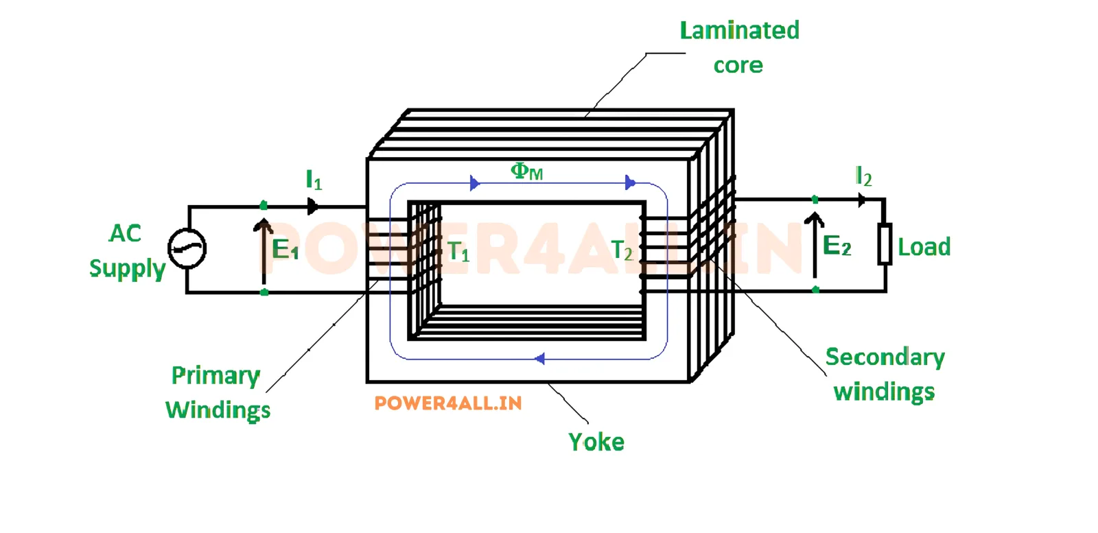
Device that transfers electrical energy between circuits through electromagnetic induction.
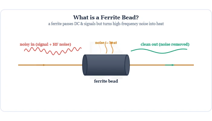
The passive EMI/RFI component that passes DC & signals but turns high-frequency noise into heat. Covers impedance vs frequency (rated at 100 MHz), the equivalent R-L-C circuit, types, how to choose one, the bead + capacitor LC filter, and ferrite bead vs inductor vs choke.
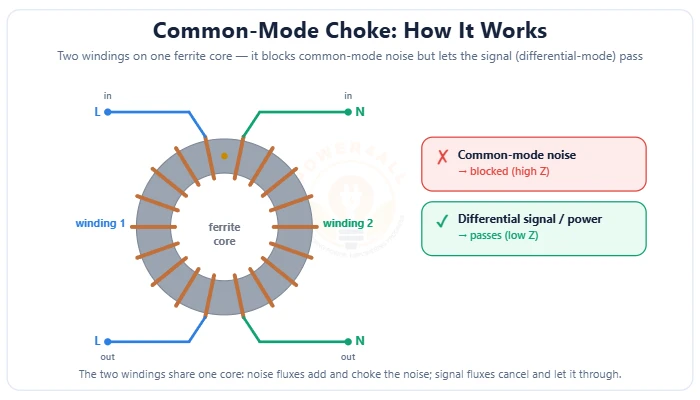
The two-winding EMI-suppression inductor that blocks common-mode noise but passes the signal — common-mode vs differential-mode, dot convention, impedance vs frequency, the X/Y-capacitor EMI filter, and how to choose one.
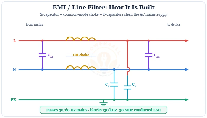
Mains low-pass filter that blocks conducted EMI with X/Y caps & a common-mode choke.
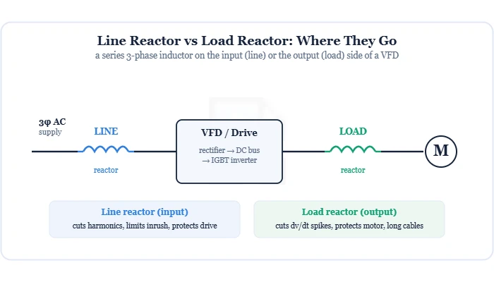
Series inductors that smooth drive current and suppress harmonics.
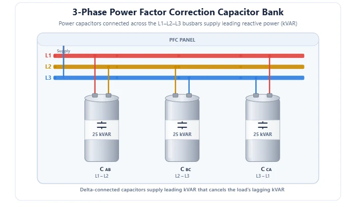
The bank of power capacitors that supplies leading reactive power (kVAR) to raise power factor — how it works, kVAR sizing, fixed vs automatic (APFC) vs detuned banks, and star vs delta connection.
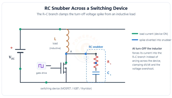
The small R–C (or R–C–D) circuit across a power switch that clamps the turn-off voltage spike and damps ringing — RC vs RCD snubbers, the flyback leakage clamp, design formulas for the resistor and capacitor, the SOA, and applications.
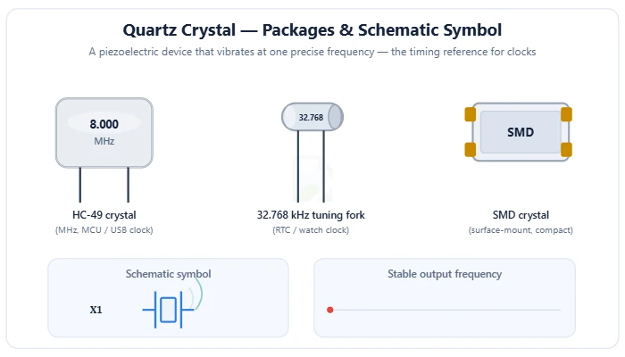
The quartz crystal and ceramic resonator that vibrate at one precise frequency to clock every device — the piezoelectric effect, the equivalent circuit, series vs parallel resonance, the Pierce oscillator, load capacitance and ppm accuracy.
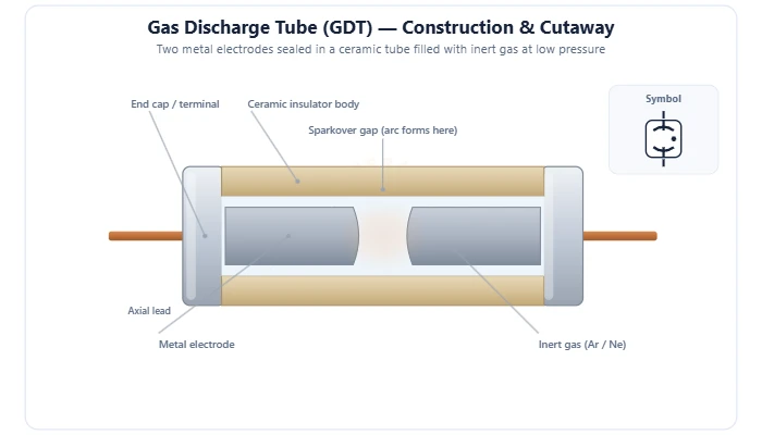
The gas-filled spark-gap surge arrester that stays open until a spike hits, then ionises and crowbars the surge to earth — sparkover, glow & arc, the V–I curve, 2 vs 3 electrode, GDT vs MOV vs TVS, and hybrid SPDs.
Device physics, diodes, transistors, thyristors and integrated circuits.
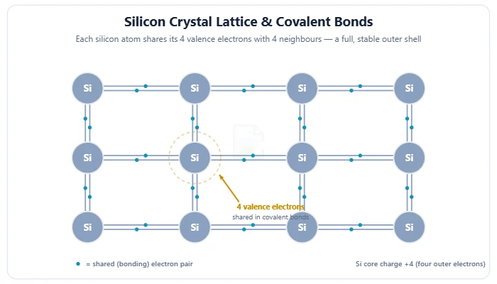
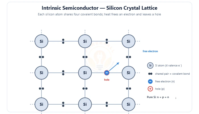
The material between a conductor and an insulator that powers all electronics — the silicon crystal & covalent bonds, energy bands and the band gap, electrons & holes, doping into N-type & P-type, and the P–N junction.
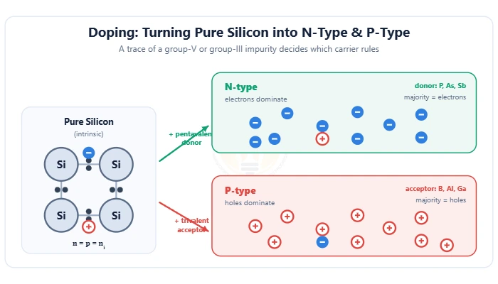
Pure vs doped semiconductors — covalent bonds & electron-hole pairs, the energy band gap & Fermi level, n-type (donor) vs p-type (acceptor), majority/minority carriers and the mass-action law n·p = ni2.
How a trace of impurity turns pure silicon into engineered material — n-type donors vs p-type acceptors, donor/acceptor ionization, dopant elements, doping methods (diffusion, ion implantation, epitaxy) and doping levels.
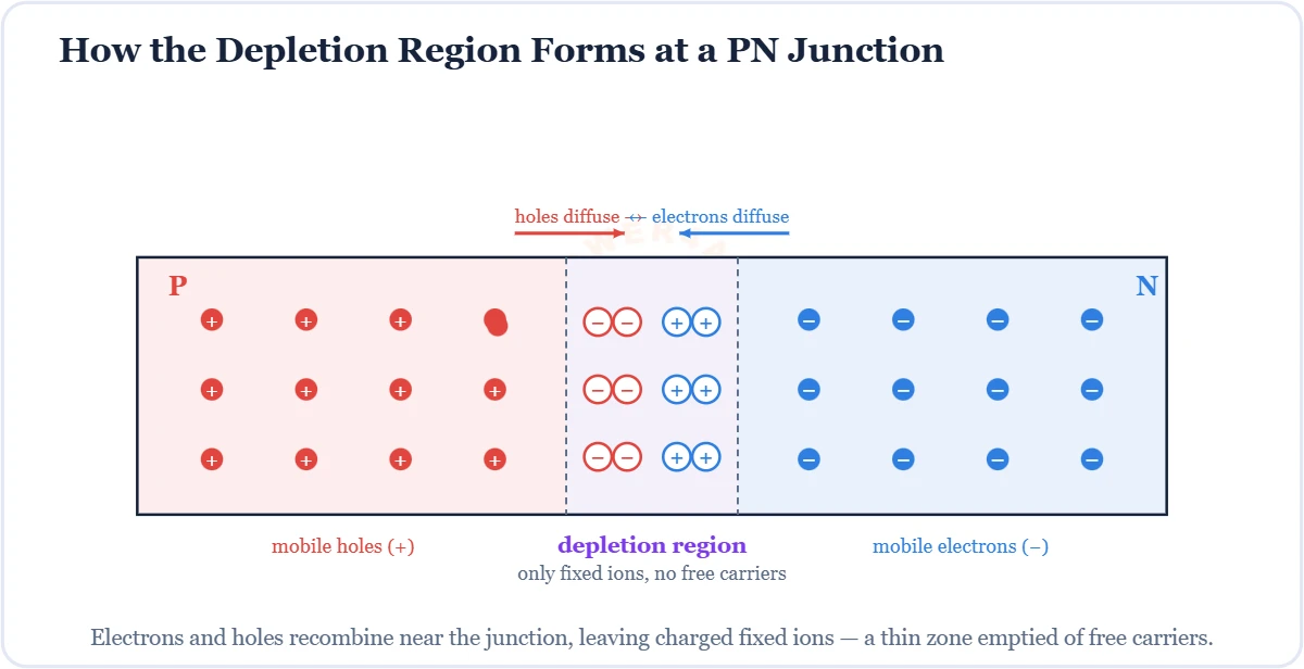
Where P-type meets N-type to form the basic diode — the depletion region & barrier potential (0.7 V), forward vs reverse bias, the V-I curve and breakdown.
The carrier-free space-charge zone at a PN junction — formation, barrier potential (0.7 V Si), forward/reverse bias, depletion width & junction capacitance.
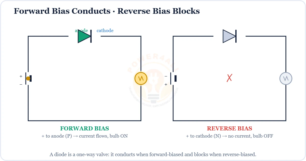
How a diode conducts or blocks — forward bias (ON, above 0.7 V), reverse bias (OFF, tiny leakage), the I-V characteristic, knee voltage & breakdown.
Why materials conduct or not — the valence & conduction bands, the forbidden band gap (Eg), conductor vs semiconductor vs insulator, the Fermi level and doping.
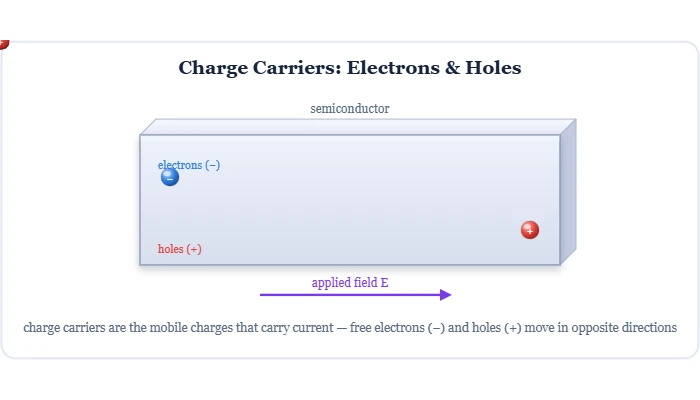
The mobile charges that carry current — free electrons & holes in semiconductors, electrons in metals, ions in electrolytes. How holes move, majority/minority carriers, drift & diffusion.
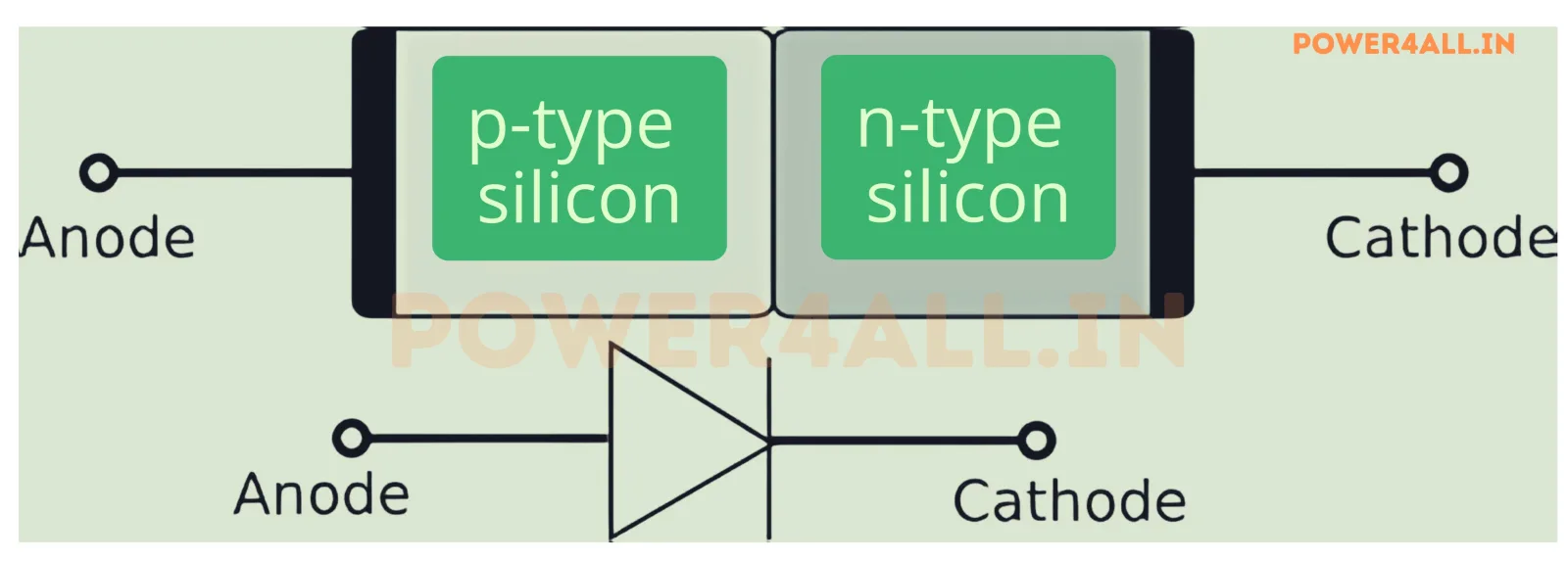
Fundamental semiconductor device allowing current flow in one direction.
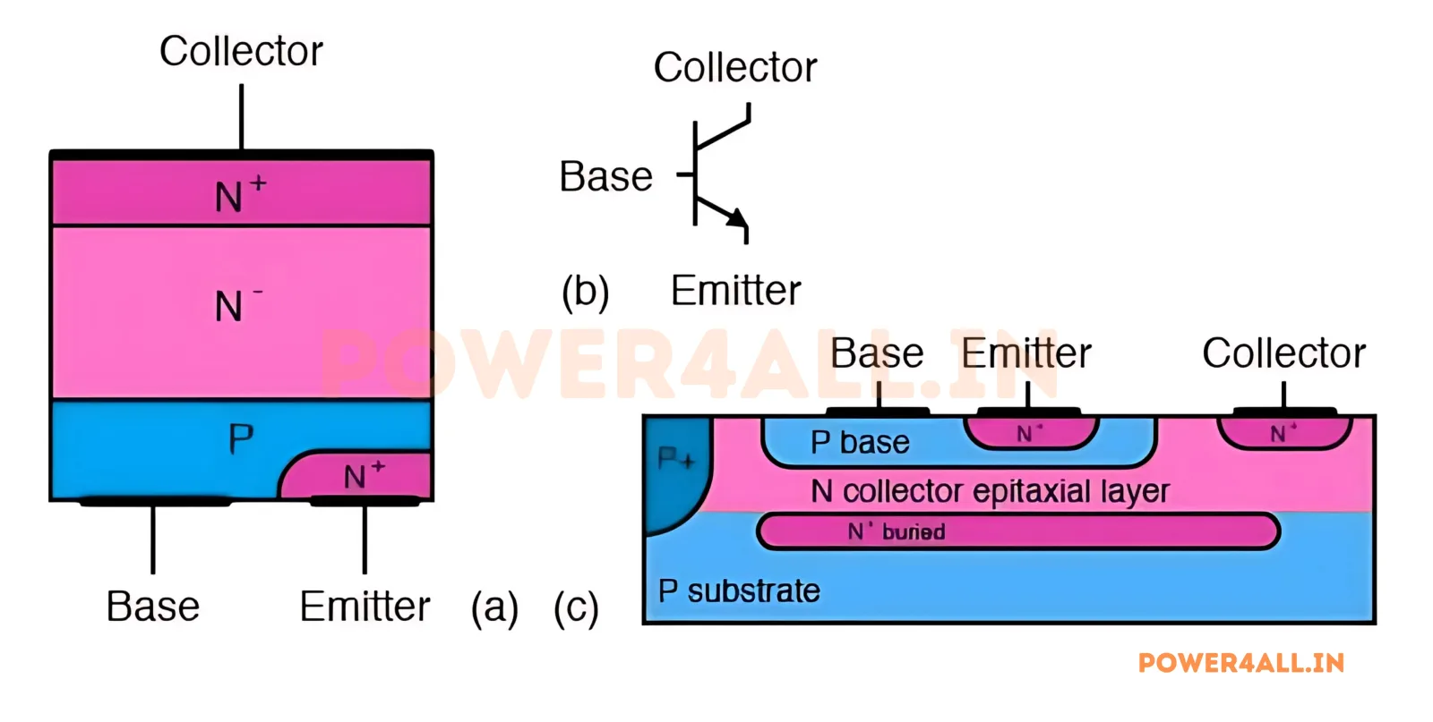
Bipolar Junction Transistor for amplification and switching applications.
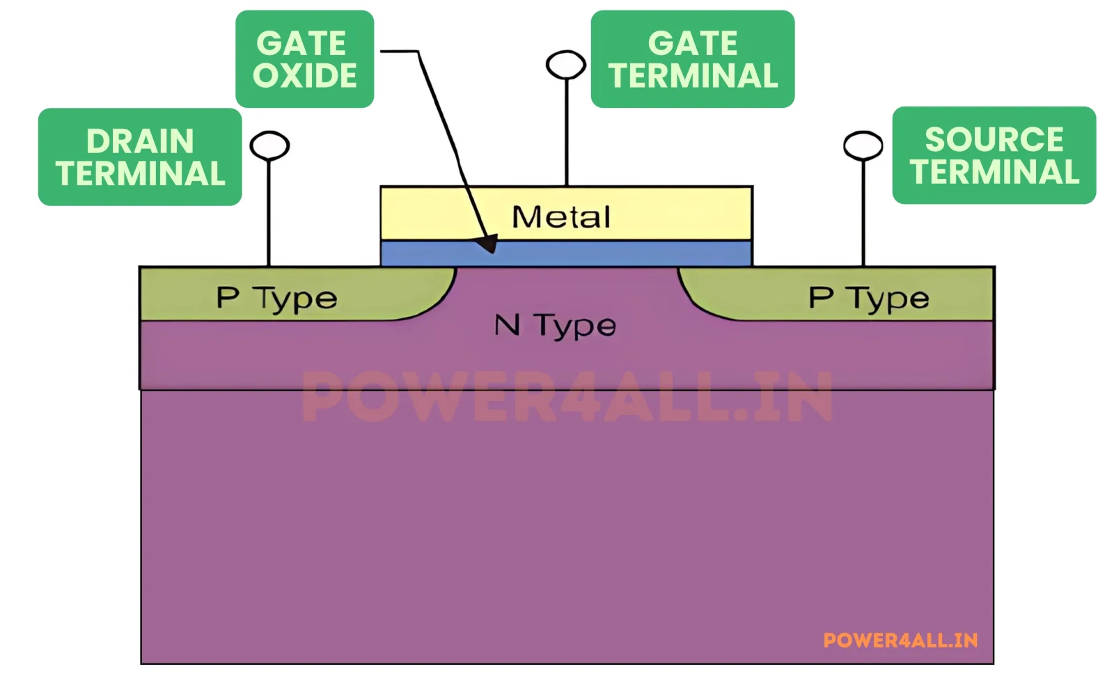
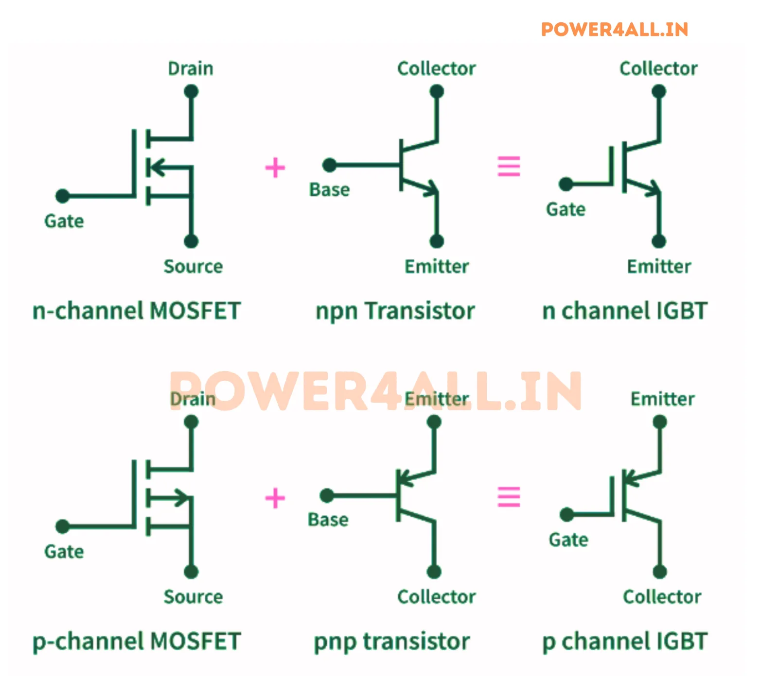
Metal-Oxide-Semiconductor Field-Effect Transistor for efficient switching.
Insulated Gate Bipolar Transistor combining MOSFET and BJT advantages.
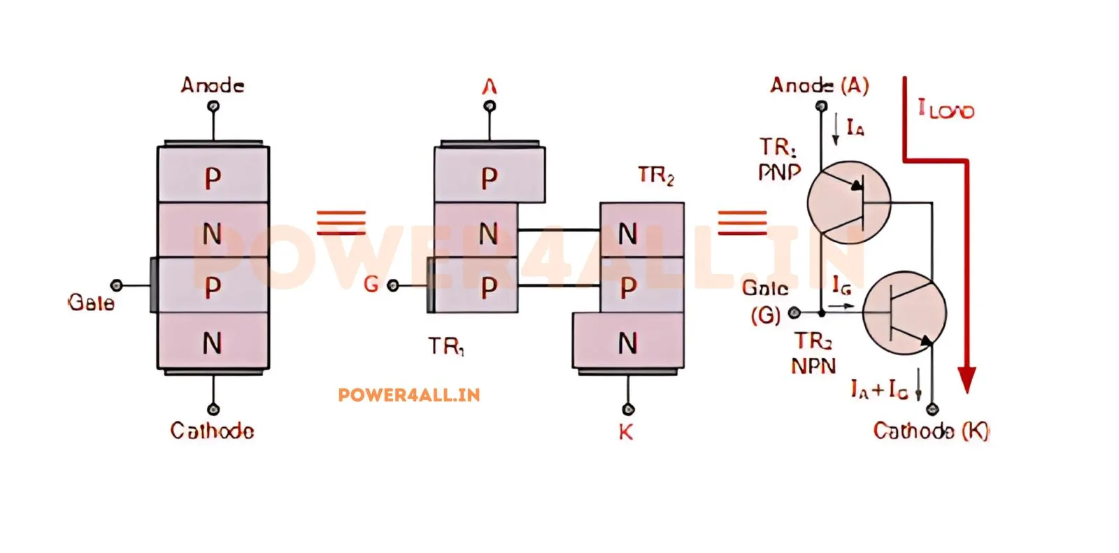
Silicon Controlled Rectifier - a powerful semiconductor switching device.
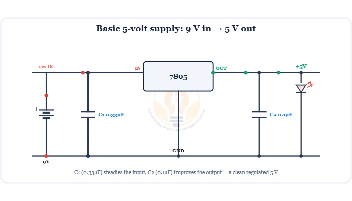
The chip that makes a fixed power rail: a 7805 gives a steady +5 V from messy DC, and an LDO does it with tiny dropout. Pinout, the basic circuit, dropout & heat, 78xx vs LDO — plus three buildable projects.
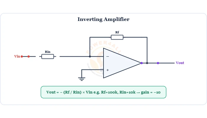
The core analog building block: a high-gain differential amplifier. With two resistors it becomes an amplifier, buffer, adder, subtractor or comparator. Symbol, 741 pinout, the golden rules and every core circuit with gain formulas.
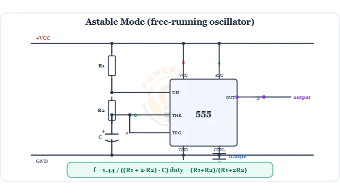
The most popular timer chip: with a few resistors and a capacitor it becomes an oscillator, one-shot timer or flip-flop. Pinout, internals, the astable/monostable/bistable modes with formulas, waveforms and an LED-blinker project.
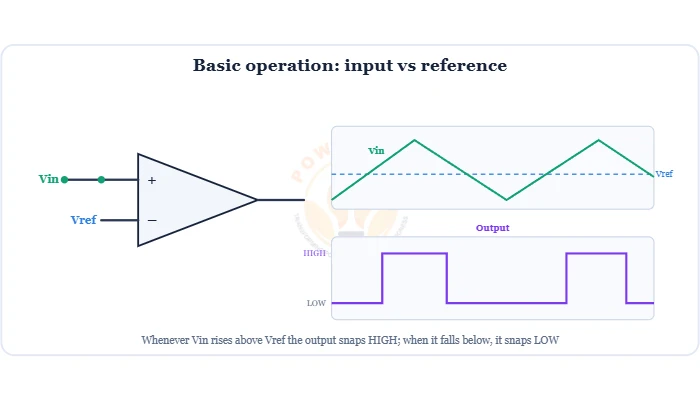
The circuit that asks “is this voltage bigger than that one?” It snaps its output HIGH or LOW at a threshold. Symbol, comparator vs op-amp, hysteresis (Schmitt trigger), window & open-collector types, the LM393, plus a light-sensor project.
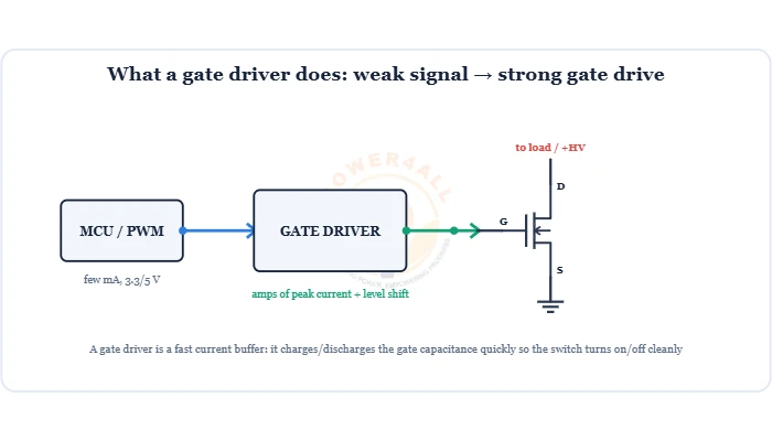
The muscle that switches power MOSFETs & IGBTs: a fast current buffer + level shifter. Why it's needed (gate charge), low-side vs high-side, the bootstrap supply, half-bridge dead-time, the gate resistor, isolated drivers and the IR2110.
Breakers, switchgear, relays, wiring and earthing.
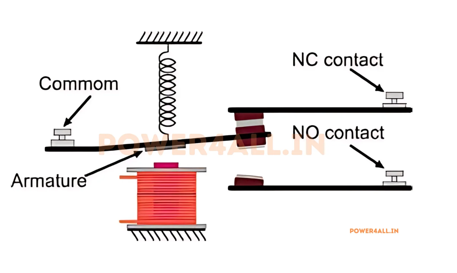
Electrically operated switch that uses electromagnetic principles for control.
Arduino, ESP32, STM32, 8051, PIC and Raspberry Pi boards.
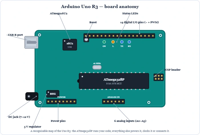
The most popular microcontroller board, built on the 8-bit ATmega328P. Full board anatomy, a complete labelled pinout with every pin explained, power & programming, the UART/SPI/I2C buses, plus code examples and beginner mini-projects.
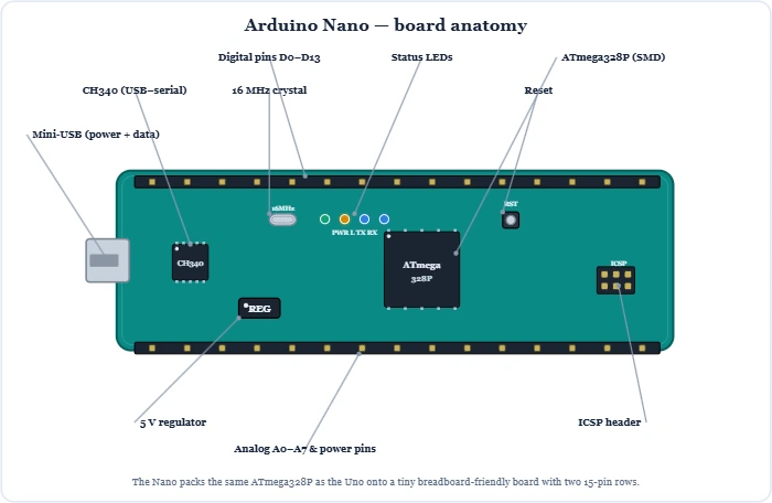
The breadboard-friendly Arduino: the same 8-bit ATmega328P as the Uno in a tiny board, with two extra analog pins. Full board anatomy, a complete labelled pinout with every pin explained, power & programming, a Nano vs Uno comparison, plus code and mini-projects.
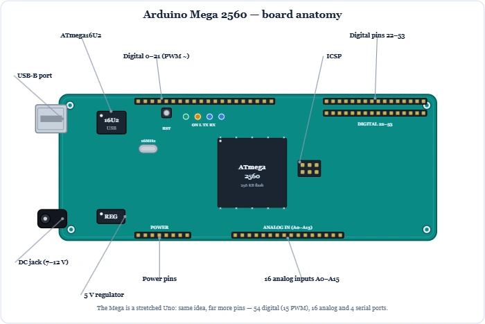
The big-board Arduino, built on the ATmega2560. When the Uno runs out of room: 54 digital pins, 16 analog inputs, four serial ports and 256 KB flash. Full board anatomy, a complete labelled pinout with every pin explained, the buses, a Mega vs Uno vs Nano comparison, plus code and mini-projects.
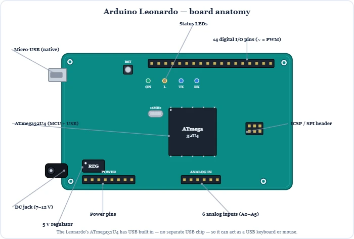
The Arduino that can be a USB keyboard or mouse. Built on the ATmega32U4 with native USB, so it needs no separate USB chip. Full board anatomy, a complete labelled pinout with every pin explained, the HID trick, a Leonardo vs Uno comparison, plus code and mini-projects.
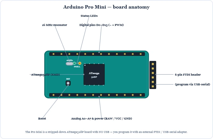
The smallest, cheapest ATmega328P board — with no USB. You program it with an external FTDI adapter. Full board anatomy, a complete labelled pinout with every pin explained, FTDI programming, the 5V vs 3.3V versions, a Pro Mini vs Uno comparison, plus code and mini-projects.
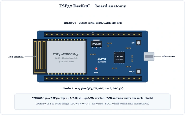
The Wi-Fi + Bluetooth microcontroller behind countless IoT projects. Dual-core 240 MHz, 520 KB RAM and a rich set of peripherals. The DevKitC board and WROOM-32 module, a complete 38-pin pinout with every GPIO explained, safe vs strapping pins, ADC/DAC, touch, PWM, deep sleep, plus code and mini-projects.
No topics match your search or filter.