Voltage Regulator IC (78xx & LDO)
The workhorse chip behind almost every gadget's power rail. A voltage regulator IC turns messy, higher DC into a rock-steady fixed voltage — a 7805 gives a clean +5 V, an LDO does it with barely any headroom. Learn the pinout, how it works, the essential circuit, dropout, heat — and build three real projects.
Complete Learning Path — Voltage Regulator IC
From what it is and its pinout, to how it works, the basic circuit, the 78xx family, dropout, LDO vs linear, heat — and three buildable projects
What is a Voltage Regulator IC?
A voltage regulator IC is a tiny chip that takes a varying, higher DC voltage and turns it into a steady, fixed lower DC voltage. It hides all the control circuitry inside one package, so you get a clean rail with just a couple of capacitors.
The most famous family is the 78xx series — the 7805 (+5 V) is in countless projects. Its close cousin, the LDO (low-dropout regulator), does the same job while wasting far less voltage, which is why battery gadgets love it.
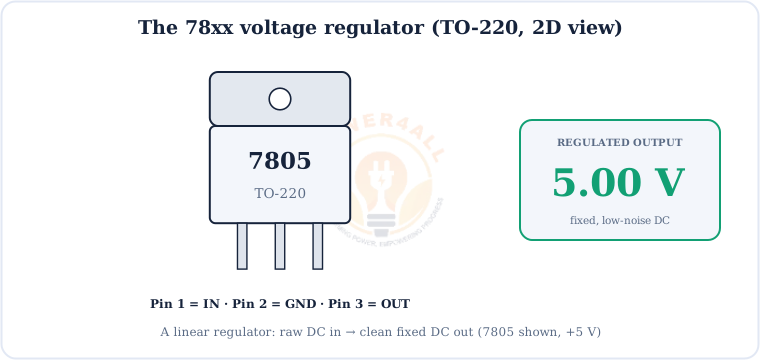
Linear regulator = a smart variable resistor
A 78xx/LDO is a linear regulator: it continuously adjusts an internal pass transistor to “burn off” the extra voltage and hold the output steady. Simple and low-noise — but the dropped voltage becomes heat.
Pinout — IN, GND, OUT
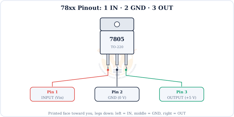
The 78xx has just three pins. Get them right and the rest is easy.
Don't swap IN and OUT
Reversing input and output (or the polarity) can destroy the chip. Double-check the orientation — the metal tab is internally connected to GND (pin 2) on a 78xx.
How It Works Inside
Inside is a small feedback control loop: a voltage reference, an error amplifier, a series pass transistor and a feedback divider work together to hold the output fixed.
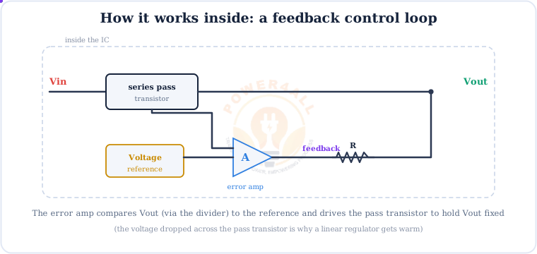
If the output tries to rise, the error amplifier throttles the pass transistor back; if it sags, the amplifier opens it up. This happens continuously, giving a smooth, low-noise output — the voltage dropped across that pass transistor is what turns into heat (see power dissipation).
The Basic Circuit
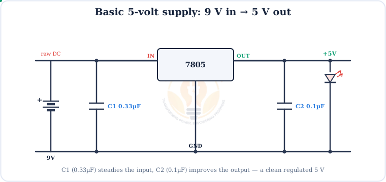
A working 5 V supply needs only the regulator and two capacitors.
The 78xx / 79xx Family
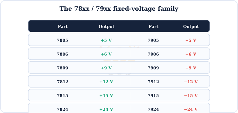
The last two digits are the output voltage. The 78xx are positive; the matching 79xx are negative.
Dropout Voltage
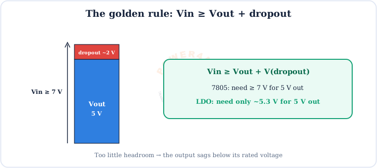
A regulator can only work if the input is high enough. The dropout voltage is the minimum headroom it needs above the output.
Linear 78xx vs LDO
An LDO is a linear regulator built to need very little headroom — perfect when the input is only slightly above the output.
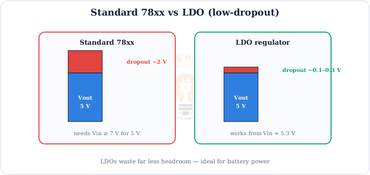
Common LDOs include the AMS1117 (fixed 3.3 V/5 V/1.2 V versions) and many low-power parts for sensors and microcontrollers. When running from a battery or a USB 5 V rail, an LDO keeps far more of your energy.
Power Dissipation & Heatsinks
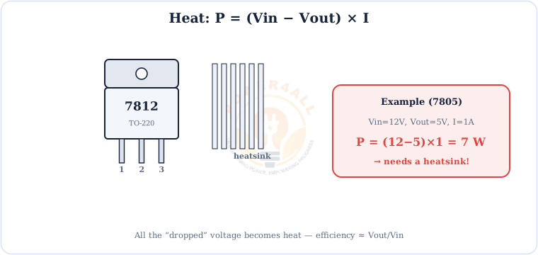
Every volt a linear regulator drops becomes heat. Know the number before you build.
Tip: keep the drop small
Feed a 7805 from ~7–9 V rather than 12 V when you can — less wasted heat. For big drops or high current, use a switching regulator instead.
Projects You Can Build
Theory done — here are three practical builds, from a first 5 V supply to an adjustable bench source.
Project 1 — 9 V Battery to 5 V Supply
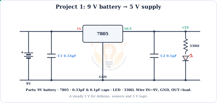
Parts & steps
Parts: 9 V battery · 7805 · 0.33 µF & 0.1 µF capacitors · LED · 330 Ω resistor · breadboard.
- Battery + → 7805 IN (pin 1); battery − → GND (pin 2).
- 0.33 µF from IN to GND; 0.1 µF from OUT to GND.
- OUT (pin 3) → LED → 330 Ω → GND. The LED lights on a clean 5 V.
Great for powering an Arduino, sensors or 5 V logic.
Project 2 — 3.3 V LDO for Sensors / MCU
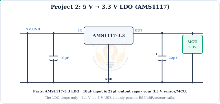
Parts & steps
Parts: AMS1117-3.3 LDO · 10 µF input capacitor · 22 µF output capacitor · your 3.3 V module.
- 5 V (USB) → LDO IN, with 10 µF IN–GND.
- LDO OUT → 22 µF OUT–GND → your 3.3 V rail.
- The LDO drops only ~1.1 V, so it runs cool at sensor currents.
Project 3 — LM317 Adjustable Supply
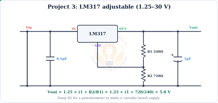
Parts & formula
Parts: LM317 · R1 = 240 Ω · R2 = 720 Ω (or a potentiometer) · 0.1 µF input & 1 µF output caps.
Swap R2 for a potentiometer and you have a variable bench supply.
How to Choose a Regulator
Output voltage
Pick the exact rail: 7805 for 5 V, AMS1117-3.3 for 3.3 V, LM317 for custom.
Headroom
Little spare voltage? Use an LDO. Plenty? A 78xx is fine.
Current
78xx handle ~1 A; check the part's rating for your load.
Heat
Compute (Vin−Vout)×I; add a heatsink or go switching if large.
Noise
Linear/LDO are low-noise — ideal for analog & RF rails.
Package
TO-220 for power, SOT-223/SMD for compact boards.
Key Terms — Glossary
| Term | Meaning |
|---|---|
| Voltage regulator IC | A chip that outputs a steady fixed DC voltage from a varying higher input. |
| 78xx | Family of fixed positive regulators; last two digits = output voltage (7805 = +5 V). |
| 79xx | The matching negative-voltage family (7905 = −5 V). |
| LDO | Low-dropout regulator — a linear regulator needing very little headroom. |
| Dropout voltage | Minimum input-to-output difference for regulation (~2 V for 78xx). |
| TO-220 | Common 3-lead through-hole package with a metal tab for a heatsink. |
| Pass transistor | The internal device that drops the excess voltage to hold the output fixed. |
| LM317 | An adjustable regulator; Vout = 1.25×(1 + R2/R1). |
| Quiescent current | The small current the regulator itself uses to operate. |
Frequently Asked Questions
Quick, expert answers to the questions people ask most about voltage regulator ICs.
What is a voltage regulator IC?
A chip that turns a varying, higher DC input into a steady, fixed lower DC output. The 78xx family gives fixed positive voltages such as +5 V from a 7805, while LDO regulators do the same with very little headroom.
What does 7805 mean in the 78xx series?
“78” marks the positive fixed-regulator family and the last two digits are the output voltage. So 7805 = +5 V, 7809 = +9 V, 7812 = +12 V. The 79xx family gives the matching negatives.
What is the pinout of a 7805?
Holding a TO-220 with the printed face toward you and legs down: pin 1 (left) = INPUT, pin 2 (middle) = GROUND, pin 3 (right) = OUTPUT. The metal tab is connected to GND.
What capacitors does a 7805 need?
About 0.33 µF from input to ground and 0.1 µF from output to ground. The input cap prevents oscillation; the output cap improves transient response.
What is dropout voltage and the minimum input?
Dropout is the minimum input-to-output headroom. A standard 78xx needs ~2 V, so a 7805 needs ≥ 7 V in. An LDO needs only ~0.1–0.3 V.
What is the difference between a 78xx and an LDO?
Both are linear, but an LDO needs far less headroom — a 78xx wastes ~2 V, an LDO only a few tenths of a volt. LDOs are better for battery and low-headroom designs.
Does a voltage regulator need a heatsink?
It depends on power: P = (Vin−Vout)×I. A 7805 at 12 V, 1 A dissipates 7 W and needs a heatsink; below ~1 W it usually doesn't.
Can I get an adjustable output voltage?
Yes — use an LM317: Vout = 1.25×(1 + R2/R1). With R1 = 240 Ω and R2 = 720 Ω you get 5 V; a potentiometer for R2 makes it variable.
Conclusion & Key Takeaways
The voltage regulator IC is the simplest way to a clean, fixed power rail — a 7805 and two capacitors, and you're done.
Fixed output
7805 = +5 V, and family.
IN · GND · OUT
Three simple pins.
Two caps
0.33µF in, 0.1µF out.
Mind dropout
Vin ≥ Vout + dropout.
Mind heat
(Vin−Vout)×I.
LDO / LM317
Low headroom / adjustable.