Interleaved / Multiphase Buck Converter
Several buck converters in parallel, deliberately switched out of step with each other — so their ripples cancel, the current splits between them, and the output looks far smoother than any one of them ever could.
- Introduction
- What is an Interleaved / Multiphase Buck?
- Circuit Diagram & Construction
- The Interleaving Principle
- Modes of Operation
- Interleaving Waveforms (Deep Dive)
- Ripple Cancellation vs Duty Ratio
- Control & Current Sharing
- Key Parameters & Formulas
- Advantages & Disadvantages
- Applications
- Frequently Asked Questions – FAQs
- Related Topics
Introduction
A plain buck converter is a lovely simple thing, but push it to high current and the problems pile up fast: one inductor and one pair of switches have to carry all of the current, the ripple gets big, the output capacitor has to be huge to swallow it, and all the heat comes out of one small spot on the board.
The fix is refreshingly simple — use several buck converters side by side, all feeding the same output. But the clever part is not switching them together. Instead each one is switched slightly out of step with the others, evenly spread around the switching period. That single trick, called interleaving, means one phase’s rising current lands on top of another’s falling current, and the ripples largely cancel each other out. The load sees a much smoother current, rippling N times faster but far smaller. This page walks through a four-leg design: the circuit, how it works, the waveforms, and the neat mathematics of exactly how much ripple disappears.
What is an Interleaved / Multiphase Buck?
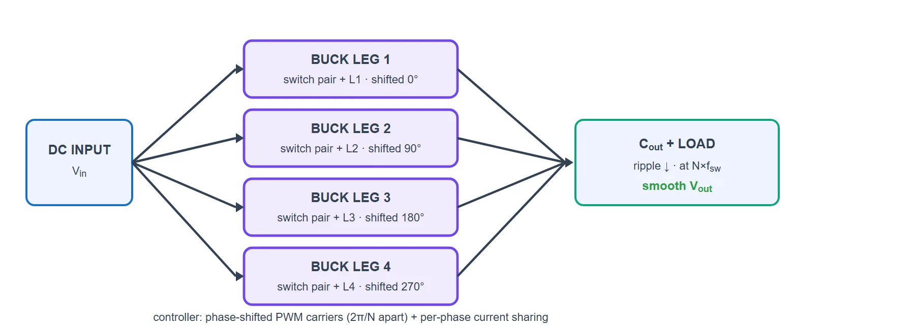
An interleaved (or multiphase) buck converter is simply N synchronised buck legs connected in parallel: they share one input, share one output, and each has its own inductor. Their gate signals are identical in shape but shifted in time by 1/N of a switching period — a phase offset of 2π/N (90° for the four-leg version on this page).
What you buy with that arrangement:
- Output ripple cancellation — the phases’ triangular ripples partly annihilate each other, so the total ripple can be a small fraction of a single phase’s.
- A higher apparent (effective) ripple frequency — the output ripples at N × fsw, even though each switch still runs at only fsw.
- Current sharing — each leg carries roughly 1/N of the load current, so smaller, cheaper devices and inductors will do.
- Spread-out heat — the losses land in N places instead of one, which is often the real reason to do it.
- Better dynamics and power density — smaller filters and a faster response to load steps.
Circuit Diagram & Construction
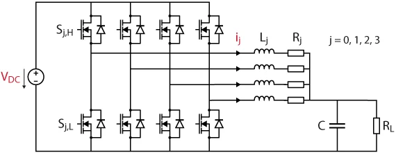
The four-leg interleaved buck is really just four ordinary synchronous buck converters bolted together:
- Input capacitor (Cin) — sits across the DC input and supplies the sharp switching current pulses that all four legs draw.
- Four half-bridge legs — each leg is a high-side switch (S1H…S4H) and a low-side switch (S1L…S4L) in series across the input. Each is a MOSFET with its body diode, and the two in a leg are driven complementary (with a dead-time). The joint between them is that leg’s switching node.
- Four inductors (L1…L4) — one per leg, from its switching node to the shared output. Each carries about a quarter of the load current.
- One output capacitor (Cout) and the load — every leg feeds this same node, which is exactly where the ripples meet and cancel.
The Interleaving Principle
Take the switching period T and divide it into N equal slices. Leg 1 starts its on-time at the beginning of the period, leg 2 starts a quarter of a period later, leg 3 halfway, leg 4 three-quarters through — a phase step of 2π/N = 90° for four legs. In the controller this is done by giving each leg the same PWM comparison but a carrier shifted by 1/N of a period.
Now think about what the output node sees. Each inductor current is a triangle: rising while its high-side switch is on, falling while it is off. Because the four triangles are staggered, at any instant some are rising while others are falling. Add them up and the up-slopes cancel the down-slopes — what is left is a much smaller ripple, wobbling N times per period instead of once. The average current is unchanged (it is simply four times one phase’s average); only the wobble shrinks.
Modes of Operation
Every leg in Figure 2 behaves exactly like a normal synchronous buck, so you only need to understand one leg — the other three are doing the same thing, just at different moments. Follow leg 1 in Figure 2 (S1H, S1L and L1). It alternates between two states:
- Mode 1 — charging (S1H ON, S1L OFF). The high-side switch connects the switching node to Vin. Looking at Figure 2, current flows from the input, through S1H, through L1 and out to the output node. The inductor now has Vin − Vout across it, so its current ramps up in a straight line, storing energy. This state lasts for the on-time, D·T.
- Mode 2 — freewheeling (S1H OFF, S1L ON). The high-side switch opens and the low-side switch closes, pulling the switching node down to the − rail (0 V). The inductor refuses to stop conducting, so its current now circulates from the − rail up through S1L, through L1 and on to the load. The voltage across L1 is now −Vout, so the current ramps down. This lasts for (1−D)·T. (For the brief dead-time before S1L turns on, the current flows through S1L’s body diode instead — same path, just a bit lossier.)
- The two switches are never on together. If they were, they would short Vin straight to the − rail. That is exactly why a dead-time is inserted between them.
- Continuous conduction (CCM). At the currents these converters are built for, the inductor current never falls to zero — it just ramps up and down about its average. That is the mode assumed throughout this page.
Now multiply that by four. Legs 2, 3 and 4 run the identical two modes, but they enter Mode 1 a quarter, a half and three-quarters of a period later respectively. So at any given instant the four legs are generally in different modes — one might be charging while two are freewheeling. Their currents all arrive at the same output node in Figure 2, and it is precisely this staggering that makes the rising and falling ramps cancel.
Interleaving Waveforms (Deep Dive)
This is the figure that explains the whole topology. Four gate signals, 90° apart; four inductor currents doing exactly what Modes 1 and 2 say they should; and then their sum — which is where the magic shows up.
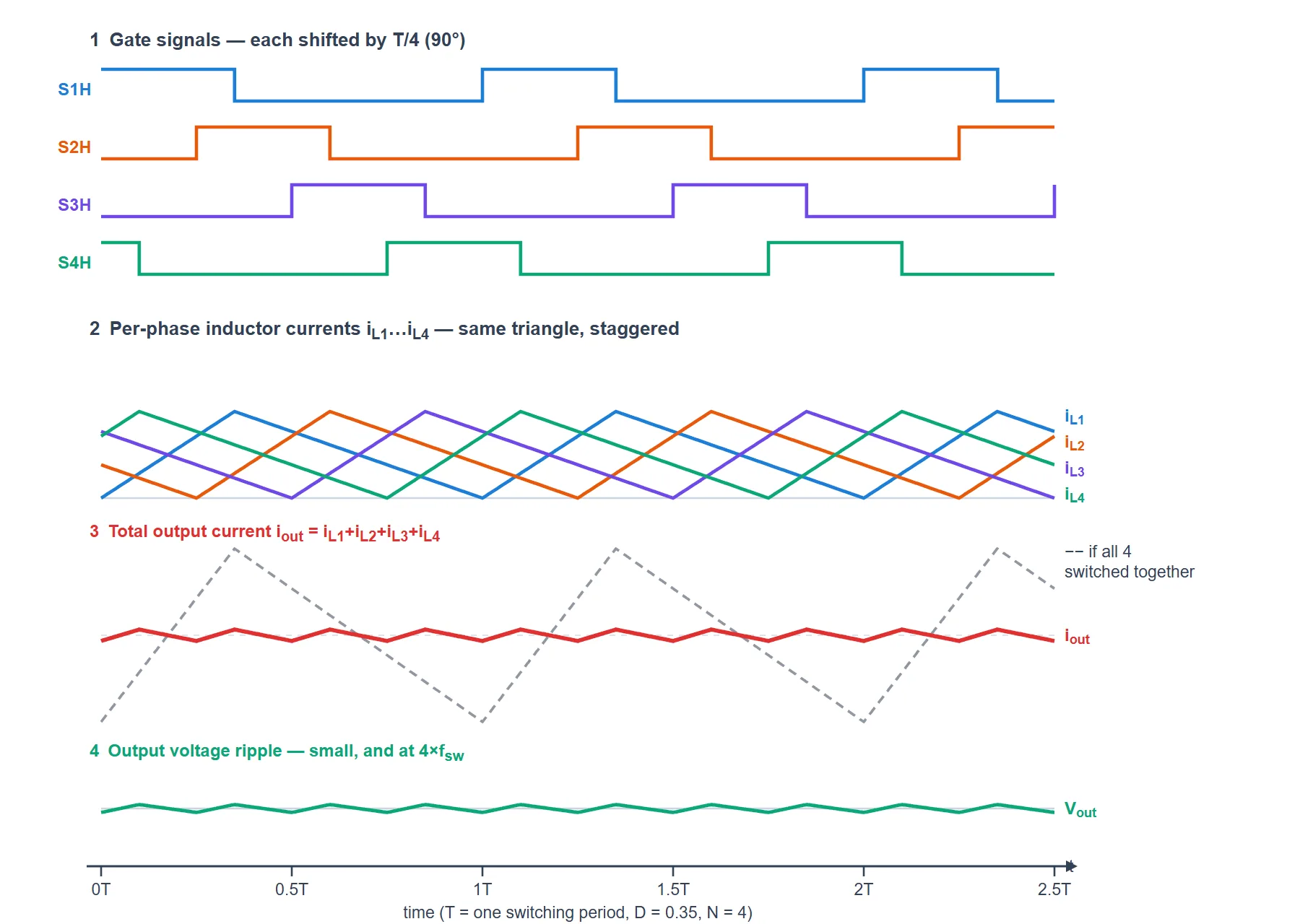
- Row 1 — the gates: identical pulses, each delayed by T/4. Nothing else about the converter changes; this delay is the interleaving.
- Row 2 — the phase currents: each is the classic buck triangle, rising during its own Mode 1 and falling during Mode 2. Notice that no individual ripple got any smaller — every leg still has its full swing.
- Row 3 — the payoff: add the four and the ramps fight each other. The red total barely moves, and it wobbles four times per period. The dashed grey trace is the same converter with the interleaving switched off (all four gates aligned): the ripple would be about fifteen times bigger — and four times slower. That gap is the entire benefit of interleaving. (With the gates aligned the total ripple is simply 4×ΔIL; interleaved it is only about 0.26×ΔIL at this duty ratio — read straight off the curve in Figure 4.)
- Row 4 — the output voltage: the capacitor only has to absorb that small, fast ripple, so Vout stays very flat. A smaller, cheaper output capacitor now does the same job.
Ripple Cancellation vs Duty Ratio
Here is the part that surprises people: how much ripple cancels depends on the duty ratio. At certain duty ratios the cancellation is perfect — the output ripple falls to exactly zero. Those sweet spots sit at D = k/N (for a four-leg design: 0.25, 0.5 and 0.75). Between them the cancellation is partial, and it always beats a single phase.
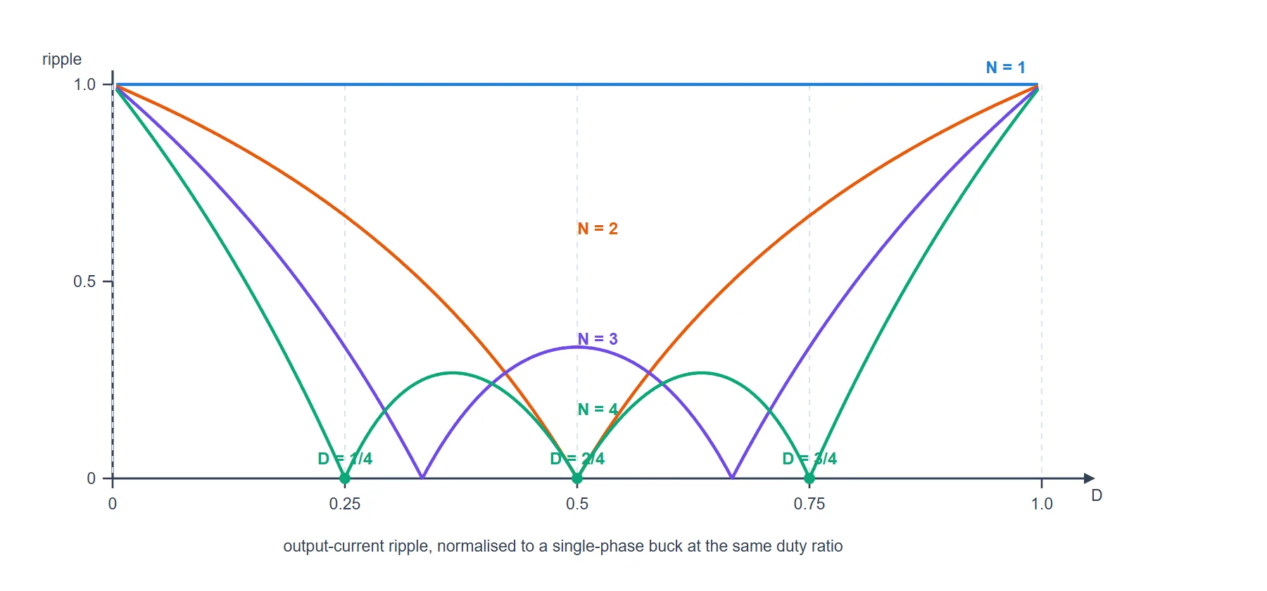
- Why zero is even possible: at D = k/N the rising ramps and falling ramps line up so perfectly that, added together, they produce a completely flat total. The individual inductors are still rippling like mad — the sum just happens to be constant.
- More legs, less ripple — almost everywhere. The N = 4 curve sits below N = 3, which sits below N = 2. Adding legs also adds more zero-crossings, so you are never far from a sweet spot.
- Design tip: if your conversion ratio is fixed and you get to choose N, pick N so that your operating D lands on (or near) a k/N point — you get the ripple almost for free.
- The worst case sits midway between two zeros, and even there the multiphase converter beats the single phase comfortably.
Control & Current Sharing
Interleaving only works if the legs actually share the current. Two legs with slightly different inductors or switch resistances will happily drift apart — one hogs the current and overheats while another loafs. So a multiphase controller does two jobs:
- Phase-shifted carriers: each leg gets its own PWM carrier, offset by 1/N of a period. This is what creates the interleaving in the first place.
- Per-phase current control: each leg has its own current measurement and its own PI regulator, so every phase is driven to the same current reference. That is what forces genuine current sharing rather than hoping the legs match.
- Sampling in the middle of the ripple: here is the subtlety. To read a phase’s average current you must sample exactly in the middle of its triangular ripple — that is where the instantaneous value equals the average. But the four ripples are staggered, so their midpoints happen at four different instants. One shared sampling instant would read four different points on four different ripples and the controller would think the phases were unbalanced when they are not. The fix is N separate sampling instants, one per phase, each aligned to its own ripple midpoint.
- An outer voltage loop then sits on top, setting the common current reference that all the phases follow.
Key Parameters & Formulas
| Quantity | Formula & Value |
|---|---|
| Output voltage (per leg and overall) | Vout = D · Vin (same as an ordinary buck) |
| Phase shift between legs | 2π/N (90° for N = 4) |
| Current per leg | IL,avg = Iout / N |
| Ripple in ONE inductor | ΔIL = Vout(1 − D) / (L · fsw) — unchanged by interleaving |
| Apparent output ripple frequency | fripple = N · fsw |
| Zero-ripple duty ratios | D = k/N, k = 1…N−1 (0.25, 0.5, 0.75 for N = 4) |
| Normalised output ripple | K = [(m+1 − ND)(ND − m)] / [ND(1 − D)], m = floor(ND) |
| Reference build | 4 legs, half-bridge modules, load step 20 → 40 A |
Advantages & Disadvantages
Advantages
- Much smaller output ripple — and it can be driven to zero at D = k/N.
- Ripple at N×fsw — so a smaller output capacitor and filter do the same job, without switching any device faster.
- Current shared N ways — smaller inductors and cheaper switches, and the heat is spread across the board instead of concentrated.
- Faster transient response and higher power density.
- Graceful scaling — need more current? Add another identical leg.
Disadvantages
- N times the hardware — N inductors, N switch pairs, N gate drivers and N current sensors.
- Current sharing must be enforced; component tolerances alone will not balance the phases.
- Trickier control and sampling — N carriers and N sampling instants to get right.
- Ripple benefit depends on D — sitting midway between two k/N points gives you the least cancellation.
- Still a buck — step-down only and non-isolated.
Applications
- CPU / GPU voltage regulator modules (VRMs) — the classic case: hundreds of amps at about a volt, which is only practical multiphase.
- EV chargers and battery chargers, including the DC-DC stage of a fast charger with intermediate energy storage.
- Battery and supercapacitor interfaces in storage systems.
- High-current industrial and telecom supplies, and point-of-load converters generally.