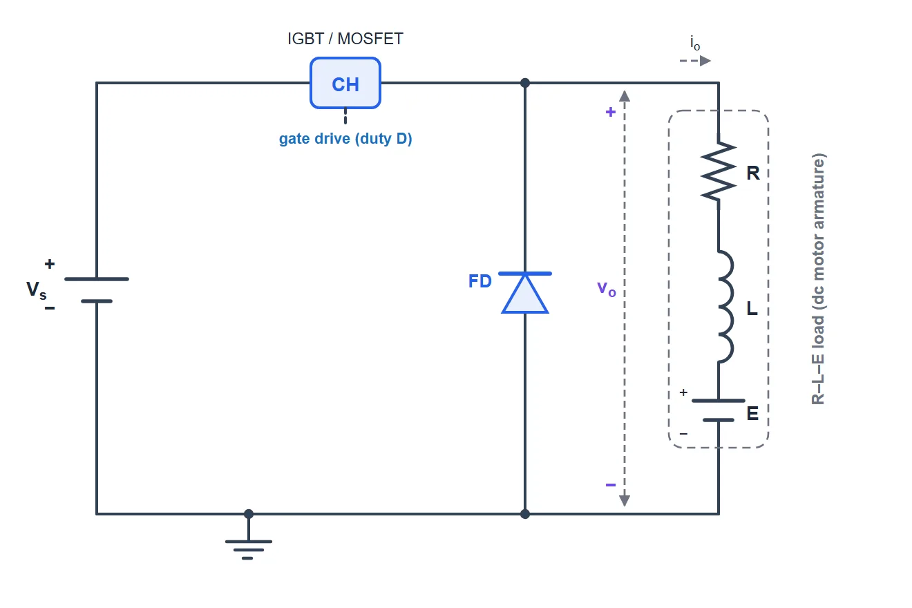
What is a Class A (first-quadrant) chopper?
A Class A chopper is the simplest DC-DC chopper: a single controlled switch (an IGBT or MOSFET) connects a DC source Vs to the load for a fraction D of every switching period, and a freewheeling diode carries the inductive load current while the switch is off. It is a step-down converter — the average output voltage is always between 0 and Vs — and because both the output voltage and the load current stay positive, it works only in the first quadrant (forward motoring). It is the standard way to control the speed of a separately-excited DC motor from a fixed DC supply, as in battery vehicles, trolley and metro traction and DC drives.
Output voltage, current & ripple
Here D is the duty cycle (0–1), Vs the source voltage, E the motor back-EMF and R, L the armature resistance and inductance. When the switch turns on the current rises (the source drives Vs − E − iR across the inductance); when it turns off the freewheeling diode conducts and the current decays. This simulator integrates the real R-L-E load through both states, runs to steady state, and compares the measured average voltage to D·Vs in the accuracy panel.
Continuous vs discontinuous conduction
With enough inductance or load the current never reaches zero — continuous conduction (CCM) — and Vo = D·Vs holds exactly. If the load is light or the back-EMF is high, the current can decay to zero before the next switch-on: discontinuous conduction (DCM), where the output voltage rises toward the back-EMF and the simple formula no longer applies. The simulator flags CCM or DCM live and only compares against D·Vs in CCM.
Advanced options in this simulator
- Duty & frequency: sweep the duty cycle and chopper frequency and watch the average voltage and current ripple respond.
- Motor model: resistive, inductive (R-L) or with a back-EMF (R-L-E) to model a real DC motor.
- Device model: add a switch saturation drop, a diode forward drop and an on-resistance; the accuracy check stays locked to the ideal Vo = D·Vs.
- Four-quadrant map: a live plot of the operating point (Vo, Io) — Class A stays in Quadrant I.
- Ripple spectrum: a real FFT of the output voltage or the load current, with harmonics at multiples of the chopper frequency.
- Export & capture: download the full waveform data as CSV, a text report, or a PNG screenshot of the scope.
The five chopper classes
| Class | Quadrants | Average output | Use |
|---|---|---|---|
| Class A | I (V+, I+) | Vo = D·Vs | Forward motoring (step-down) |
| Class B | II (V+, I−) | Vo = (1−D)·Vs | Regenerative braking |
| Class C | I & II | Vo = D·Vs | Motoring + braking |
| Class D | I & IV | Vo = (2D−1)·Vs | ±V, one current direction |
| Class E | I–IV | Vo = (2D−1)·Vs | Full four-quadrant drive |
Explore the others: Class B, Class C, Class D and Class E chopper simulators. For the full theory see the Class A chopper tutorial.
Applications
Battery-electric vehicle and forklift drives, trolleybus and metro traction, DC-motor speed control, switch-mode power supplies and any adjustable DC supply that only needs one-directional (motoring) operation.
Frequently asked questions
What is the average output voltage of a Class A chopper?
Vo = D·Vs, where D is the duty cycle and Vs the source voltage. The average current is (D·Vs − E)/R.
Why is it called a first-quadrant chopper?
Both the output voltage and the load current are always positive, so the operating point stays in Quadrant I of the voltage–current plane (forward motoring).
How do I reduce the current ripple?
Increase the chopper frequency or the load inductance — the peak-to-peak ripple is ≈ Vs·D(1−D)/(f_c·L).
When does discontinuous conduction occur?
At light load, low inductance, low duty or high back-EMF the current falls to zero within a period. The simulator flags DCM and stops comparing against Vo = D·Vs.