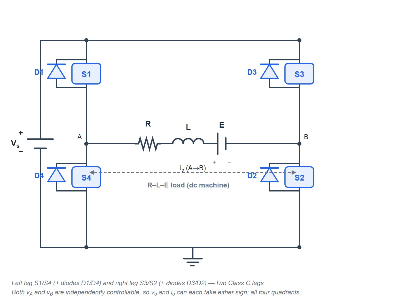
What is a Class E (four-quadrant) chopper?
A Class E chopper is a full H-bridge — four controlled switches with four anti-parallel diodes, effectively two Class C legs. By choosing which diagonal pair of switches conducts it can apply +Vs or −Vs to the load, and the anti-parallel diodes let the current flow in either direction. Combining both voltage polarities with both current directions gives full four-quadrant operation: forward motoring, forward (regenerative) braking, reverse motoring and reverse braking. It is the standard power stage of a fully reversible DC-motor drive.
Output voltage & four-quadrant operation
With bipolar PWM the diagonal pairs apply +Vs for a fraction D of the period and −Vs for the rest, so the average is Vo = (2D−1)·Vs: zero at D = 0.5, positive (forward) above and negative (reverse) below. The motor back-EMF E then sets the current direction — below Vo the machine motors, above it the machine brakes. Move the duty and the signed back-EMF to visit all four quadrants. This simulator integrates the real R-L-E load and compares the measured average to (2D−1)·Vs.
Advanced options in this simulator
- Duty & signed back-EMF: sweep the duty through 0.5 and set the back-EMF sign to reach forward/reverse motoring and braking.
- Device model: switch and diode drops with on-resistance; the accuracy check stays locked to Vo = (2D−1)·Vs.
- Four-quadrant map: the operating point can land in any of the four quadrants.
- Ripple spectrum & export: FFT of voltage/current and CSV/report/PNG export.
The five chopper classes
| Class | Quadrants | Average output | Use |
|---|---|---|---|
| Class A | I (V+, I+) | Vo = D·Vs | Forward motoring (step-down) |
| Class B | II (V+, I−) | Vo = (1−D)·Vs | Regenerative braking |
| Class C | I & II | Vo = D·Vs | Motoring + braking |
| Class D | I & IV | Vo = (2D−1)·Vs | ±V, one current direction |
| Class E | I–IV | Vo = (2D−1)·Vs | Full four-quadrant drive |
Explore the others: Class A, Class B, Class C and Class D chopper simulators. For the full theory see the Class E chopper tutorial.
Applications
Fully reversible DC-motor drives — rolling mills, cranes, hoists, mine winders, electric traction and servo drives — where the machine must run and brake in both directions with smooth, fast transitions between quadrants.
Frequently asked questions
What is the average output voltage of a Class E chopper?
With bipolar PWM, Vo = (2D−1)·Vs. It is zero at D = 0.5, positive (forward) above and negative (reverse) below.
Why is it a four-quadrant chopper?
The H-bridge sets the voltage either polarity and the diodes carry either current direction, so the operating point can reach all four quadrants.
How do I reach each quadrant?
Set the duty above or below 0.5 for forward/reverse voltage, and set the back-EMF below or above the output for motoring/braking — the four combinations give the four quadrants.
How is it built?
As a full H-bridge — four IGBTs/MOSFETs with anti-parallel diodes, equivalent to two Class C legs.