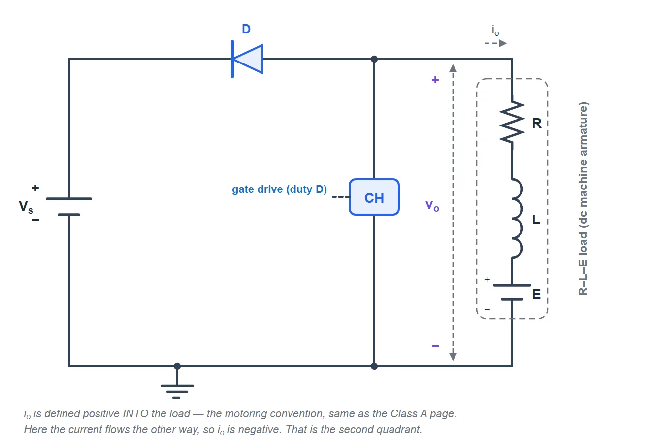
What is a Class B (second-quadrant) chopper?
A Class B chopper is a regenerative-braking DC chopper. A single controlled switch is connected across the load; when it turns on, the DC machine (running as a generator) drives current through the armature inductance and stores energy. When the switch turns off, a diode returns that energy to the DC source. The average output voltage stays positive but the load current is negative, so the operating point sits in the second quadrant — the machine brakes and feeds power back to the supply instead of dissipating it. It is the braking half of a reversible DC drive and is what lets electric vehicles and hoists recover energy.
Output voltage, braking current & ripple
Here D is the duty ratio of the switch (the fraction of each period it shorts the load), Vs the source voltage, E the motor back-EMF and R, L the armature parameters. Because braking needs E > Vo, the current is negative — energy flows from the machine to the source. This simulator integrates the real R-L-E load through both switch states, runs to steady state, and compares the measured average voltage to (1−D)·Vs in the accuracy panel.
Continuous vs discontinuous conduction
As with any chopper, enough inductance keeps the braking current continuous (CCM) and Vo = (1−D)·Vs holds. A light machine or small inductance can let the current reach zero within a period (DCM), where the simple relation breaks down. The simulator flags CCM or DCM live.
Advanced options in this simulator
- Duty & frequency: sweep the duty ratio and chopper frequency and watch the braking voltage and current respond.
- Motor model: resistive, inductive (R-L) or with a back-EMF (R-L-E) — set a high back-EMF to see strong braking.
- Device model: add a switch drop, a diode forward drop and an on-resistance; the accuracy check stays locked to the ideal Vo = (1−D)·Vs.
- Four-quadrant map: a live plot of the operating point (Vo, Io) — Class B stays in Quadrant II.
- Ripple spectrum & export: a real FFT of the output voltage or current, plus CSV, report and PNG export.
The five chopper classes
| Class | Quadrants | Average output | Use |
|---|---|---|---|
| Class A | I (V+, I+) | Vo = D·Vs | Forward motoring (step-down) |
| Class B | II (V+, I−) | Vo = (1−D)·Vs | Regenerative braking |
| Class C | I & II | Vo = D·Vs | Motoring + braking |
| Class D | I & IV | Vo = (2D−1)·Vs | ±V, one current direction |
| Class E | I–IV | Vo = (2D−1)·Vs | Full four-quadrant drive |
Explore the others: Class A, Class C, Class D and Class E chopper simulators. For the full theory see the Class B chopper tutorial.
Applications
Regenerative braking of DC drives in electric and hybrid vehicles, forklifts, cranes, hoists, mine winders and metro traction, where recovering kinetic energy to the supply improves efficiency and reduces brake wear.
Frequently asked questions
What is the average output voltage of a Class B chopper?
Vo = (1−D)·Vs. The load current (Vo − E)/R is negative because the motor back-EMF drives energy back to the source.
Why is it a second-quadrant chopper?
The average voltage is positive but the current is negative (braking), so the operating point lies in Quadrant II of the voltage–current plane.
How does it recover energy?
The switch stores energy in the inductance from the machine; when it opens, the diode forces that energy back into the DC source — regenerative braking.
When does discontinuous conduction occur?
At light braking, low inductance or extreme duty the current reaches zero within a period; the simulator flags DCM and stops comparing against Vo = (1−D)·Vs.