What is a three-phase dual converter?
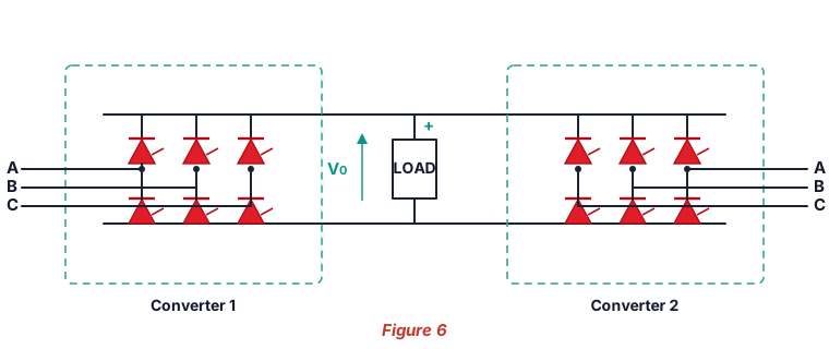
A three-phase dual converter is two three-phase fully-controlled six-pulse thyristor bridges connected in anti-parallel across the same load, as in Figure 6. Converter 1 (the positive or P-converter) can source positive load current, while Converter 2 (the negative or N-converter) sources negative current. Because each 6-pulse bridge is itself two-quadrant (it can rectify and, with an active load, invert), the anti-parallel pair covers all four quadrants of the voltage–current plane. It is the classic front-end of a reversible DC-motor drive — forward and reverse, motoring and regenerative braking — with a fast, smooth transition between them.
Output voltage, firing angles, PIV & ripple
Here Vm is the peak phase (line-to-neutral) voltage. Each bridge behaves like a 6-pulse fully-controlled converter, so its mean output is (3√3·Vm/π)cos α. To keep the two mean voltages equal in magnitude but opposite in polarity around the loop, the firing angles are constrained to α1 + α2 = 180°, giving cos α2 = −cos α1. As α1 goes from 0° to 180°, the mean load voltage swings from +3√3·Vm/π through zero (at 90°) to −3√3·Vm/π. This simulator fires both bridges accordingly, integrates the real load and compares the measured average to (3√3·Vm/π)cos α1 in the accuracy panel.
Circulating-current vs circulating-current-free operation
In circulating-current mode both bridges are gated continuously. Their averages are equal, but their instantaneous outputs differ, so a ripple voltage vr = v1 + v2 appears around the loop and drives a circulating current limited by the reactor Lr. This keeps both converters conducting for an instant, ripple-free reversal — at the cost of extra device current and reactor hardware. In circulating-current-free (non-circulating) mode only the converter that carries the load is gated, so the circulating current is zero; a short changeover delay is needed to reverse. Toggle the mode and watch the i_r trace and the four-quadrant map respond.
Advanced options in this simulator
- Four-quadrant map: a live plot of the operating point
(Vo, Io)showing which quadrant — forward/reverse motoring or braking — the drive is in. - SCR model: add a forward drop
V_fand on-resistanceR_on; the load path uses two SCRs in series (2·V_f + 2·R_on·i). The accuracy check stays locked to the ideal envelope. - Transformer: a turns ratio scales the phase voltage into both bridges.
- Load configuration: resistive, inductive (R-L) or with a signed back-EMF (R-L-E) for motoring and regeneration.
- Filter & protection: a series-L, shunt-C or LC output filter, an optional RC snubber, and a live protection-margin check of the SCR PIV and average current against the ratings you enter.
- Phase sequence & imbalance: swap the sequence or unbalance the phases and watch the ripple and harmonics change.
- Harmonic spectrum analysis: a real FFT of the output voltage (6th, 12th …) or the AC line current (5th, 7th, 11th, 13th …) with the ripple / THD figure.
- Export & capture: download the full waveform data as CSV, a text report, or a PNG screenshot of the scope.
Dual converter vs single fully-controlled bridge
| Feature | Single 6-pulse controlled bridge | Three-phase dual converter |
|---|---|---|
| Devices | 6 thyristors | 12 thyristors (two bridges) |
| Average voltage | (3√3·Vm/π)cos α | (3√3·Vm/π)cos α1 (both polarities) |
| Quadrants | 2 (±V, one current dir.) | 4 (±V and ±I) |
| Current reversal | Not possible | Yes (second bridge) |
| Circulating current | — | Optional (reactor-limited) |
| PIV | √3·Vm | √3·Vm |
See the three-phase fully-controlled 6-pulse bridge for a single bridge, the three-phase semiconverter for the half-controlled version, or the single-phase dual converter for the 1φ four-quadrant case.
Applications
Reversible DC-motor drives for rolling mills, cranes, hoists, mine winders, machine tools and electric traction — anywhere a DC machine must run in both directions and brake regeneratively. The dual converter is also used in synchronous-motor excitation and in some HVDC and battery test systems where four-quadrant DC control is required.
Frequently asked questions
What is the average output voltage of a 3-phase dual converter?
Vo = (3√3·Vm/π)cos α1 ≈ 1.654·Vm·cos α1, where Vm is the phase peak and α1 is Converter 1's firing angle. The two bridges obey α1 + α2 = 180°.
Why is α1 + α2 = 180°?
So that the two bridges present equal average voltages of opposite polarity around the loop (cos α2 = −cos α1), preventing a large DC circulating current while still allowing four-quadrant control.
What is the difference between the two modes?
Circulating-current mode keeps both bridges conducting (a reactor-limited ripple current flows between them) for fast, smooth reversal. Circulating-current-free mode gates only the active bridge, so no circulating current flows but a small changeover delay is needed.
What is the PIV of each thyristor?
PIV = √3·Vm — the peak line-to-line voltage — for every thyristor in both bridges.
Which harmonics appear?
Output-voltage harmonics at multiples of 6× the supply frequency; AC line-current harmonics of order 6k±1 (5th, 7th, 11th, 13th …). Raising α increases the harmonic content. Toggle the spectrum panel between voltage and line current.