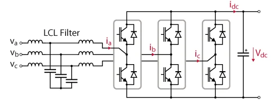
What is a PWM / active-front-end rectifier?
A PWM active-front-end (AFE) rectifier — also called a voltage-source or boost-type PWM rectifier — is a three-phase, two-level, six-IGBT bridge connected to the grid through boost inductors. It is topologically a voltage-source inverter operated as a rectifier: by switching the bridge it forces the line currents to be sinusoidal and in phase with the voltages (unity power factor) while regulating the DC-bus voltage.
Bidirectional, four-quadrant operation
Because every switch is an IGBT with an anti-parallel diode, current can flow either way. The AFE therefore rectifies when the load consumes power and regenerates — feeds power back to the grid — when the load returns energy (a decelerating motor, for example). The input power factor can also be commanded leading or lagging, so the AFE can act as a static VAr compensator.
Unity power factor and boost operation
As a boost rectifier the DC bus must exceed the line-to-line peak √3·Vm. The current controller shapes each line current into a sinusoid, giving a power factor near 1 and THD below 5%, comfortably meeting IEEE 519.
Two-level vs three-level
The AFE's two-level phase voltage has larger steps than the three-level Vienna rectifier, so for the same input filter it needs a higher switching frequency, or a larger boost inductor, to reach the same low current ripple. In return it is simpler, fully bidirectional, and uses a standard six-switch bridge.
No low-frequency ripple
As with any balanced three-phase converter the instantaneous input power p(t) = (3/2)·Vm·Im is constant, so there is no 100/120 Hz output ripple — only high-frequency switching ripple. The simulator verifies this in real time.
Applications
Regenerative motor drives, grid-tie inverters and active front ends for large drives, renewable-energy converters and battery systems. Compare the three-level Vienna rectifier and the single-phase boost PFC.
Frequently asked questions
What is a PWM / active-front-end rectifier?
A three-phase, two-level, six-IGBT boost-type voltage-source rectifier that shapes sinusoidal input currents at unity power factor and regulates a DC bus. It is a voltage-source inverter operated as a rectifier, and is fully bidirectional.
Why is it bidirectional?
Every switch is an IGBT with an anti-parallel diode, so current can flow either way. The converter rectifies when the load draws power and regenerates power back to the grid when power reverses.
How high must the DC bus be?
Above the line-to-line peak √3·Vm (about 560 V for a 400 V line), because it is a boost-type rectifier.
How is it different from a Vienna rectifier?
The AFE is a two-level six-IGBT bridge with larger voltage steps but full bidirectional power flow. The Vienna rectifier is three-level with only three controlled switches and lower THD, but it is unidirectional (rectify only).