Three-Phase Semi-Converter
A three-phase half-controlled bridge — three thyristors and three diodes — that gives smooth, adjustable DC in one direction at a lower cost than a fully-controlled converter.
- Introduction
- What is a Three-Phase Semi-Converter?
- Circuit Diagram & Construction
- How It Works (Conduction & Freewheeling)
- Output Voltage Waveforms (6-Pulse & 3-Pulse)
- Current Waveforms (Device, Freewheeling & Line)
- Average Output Voltage & Control Curve
- Effect of the Firing Angle α
- Semi-Converter vs Full-Converter (3-Phase)
- Advantages & Disadvantages
- Applications
- Frequently Asked Questions – FAQs
- Related Topics
Introduction
A three-phase full converter uses six thyristors, and every thyristor needs its own gate-drive and protection circuit. That is a lot of cost and complexity — and you only really need it if the drive must push power back into the mains (inverting). Plenty of jobs never need that. They only need a controllable DC voltage in one direction: battery chargers, electroplating lines, heaters, and simple motor drives that never regenerate.
For those jobs the three-phase semi-converter is the smarter choice. It keeps three thyristors for the control and replaces the other three with plain diodes, giving a half-controlled bridge that is cheaper, simpler to trigger, and has a better input power factor than the full converter — at the price of working in only one quadrant. This page explains the circuit, how the devices take turns conducting, why a freewheeling diode matters above 60°, and the full set of voltage and current waveforms.
What is a Three-Phase Semi-Converter?
A three-phase semi-converter (also called a three-phase half-controlled bridge) is a three-phase AC-to-DC converter made from a mix of controlled and uncontrolled devices. You start from the six-device bridge and swap half of it for diodes:
- Three thyristors (T1, T2, T3) form the top (positive) group with a common cathode. These give the phase control.
- Three diodes (D1, D2, D3) form the bottom (negative) group with a common anode. These conduct on their own.
- A freewheeling diode Dm is usually connected across the load.
The thyristors are fired at a delay angle α, which sets the output voltage. The diodes simply pass current whenever their phase is the most negative. Because the diodes and the freewheeling path never let the output go negative, the converter can only rectify — it works in a single quadrant and cannot return energy to the supply. Its average output voltage is:
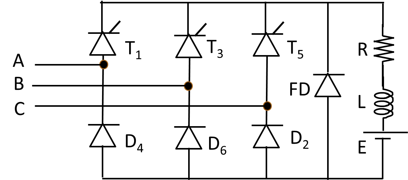
Circuit Diagram & Construction
The circuit is a normal three-phase bridge with one half replaced by diodes:
- Top group — three thyristors (T1, T2, T3) with their cathodes tied together at the positive DC terminal. Whichever phase is most positive is connected once its thyristor is fired.
- Bottom group — three diodes (D1, D2, D3) with their anodes tied together at the negative DC terminal. Whichever phase is most negative conducts automatically.
- Freewheeling diode Dm across the load, to carry the load current whenever the bridge output tries to fall below zero.
- A load that is usually inductive (a DC motor armature or a filtered supply).
How It Works (Conduction & Freewheeling)
At any instant the output voltage is the top-group voltage minus the bottom-group voltage. The two groups behave very differently:
- Top group (controlled): a thyristor only takes over after its phase becomes the most positive and after its gate is fired — a delay of α. So the positive rail is a delayed version of the “most-positive phase”.
- Bottom group (uncontrolled): a diode conducts the instant its phase becomes the most negative — no delay at all. So the negative rail always follows the “most-negative phase”.
This mix of delayed and undelayed rails gives the semi-converter its two distinct behaviours:
α > 60°: the delayed top rail drops below the bottom rail for part of each interval. The output would go negative, so the freewheeling diode Dm takes over and clamps it to zero. The output now has gaps — a 3-pulse waveform.
During a freewheeling gap the load current does not stop: it circulates through Dm while the supply is briefly disconnected. That is what keeps the output from ever going negative and makes the converter one-quadrant.
Output Voltage Waveforms (6-Pulse & 3-Pulse)
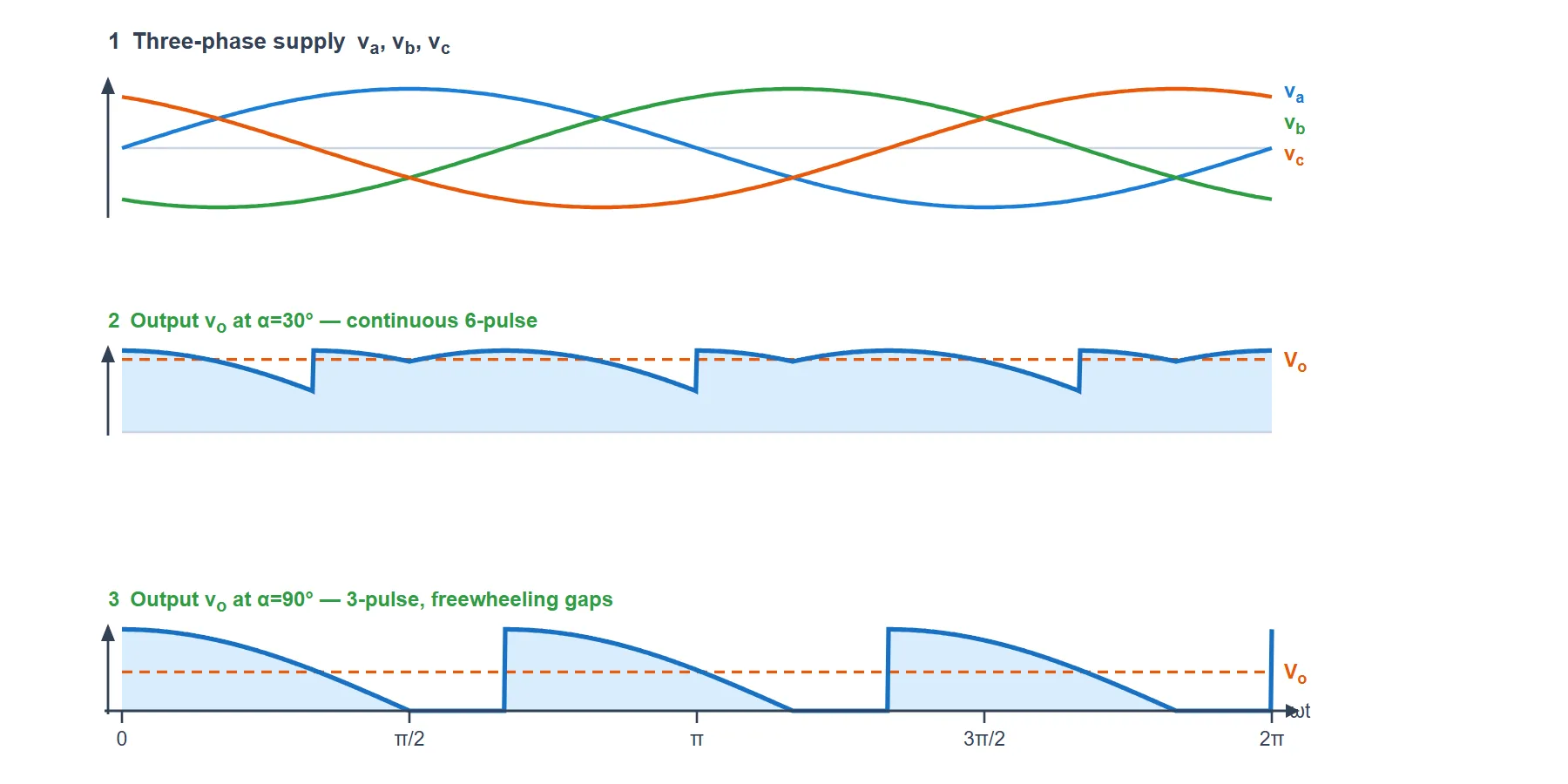
Below are the three-phase supply and the output voltage at two firing angles — α = 30° (continuous, 6-pulse) and α = 90° (freewheeling, 3-pulse). Watching the same converter at both angles is the clearest way to see how the semi-converter changes character at 60°.
Reading the Voltage Waveforms
- Supply: the three phase voltages va, vb, vc, 120° apart. The output is stitched from the tops of these (via the thyristors) and the bottoms (via the diodes).
- At α = 30°: the output never touches zero, so it is a smooth 6-pulse ripple — the semi-converter behaves just like a full converter here, and no freewheeling happens.
- At α = 90°: three times per cycle the output would go negative, so Dm clamps it to zero. You can see the flat zero gaps — the waveform is now 3-pulse. The average Vo is lower, exactly as the formula predicts.
- Never negative: in both cases the output stays at or above zero — that is the one-quadrant nature of a semi-converter.
Current Waveforms (Device, Freewheeling & Line)
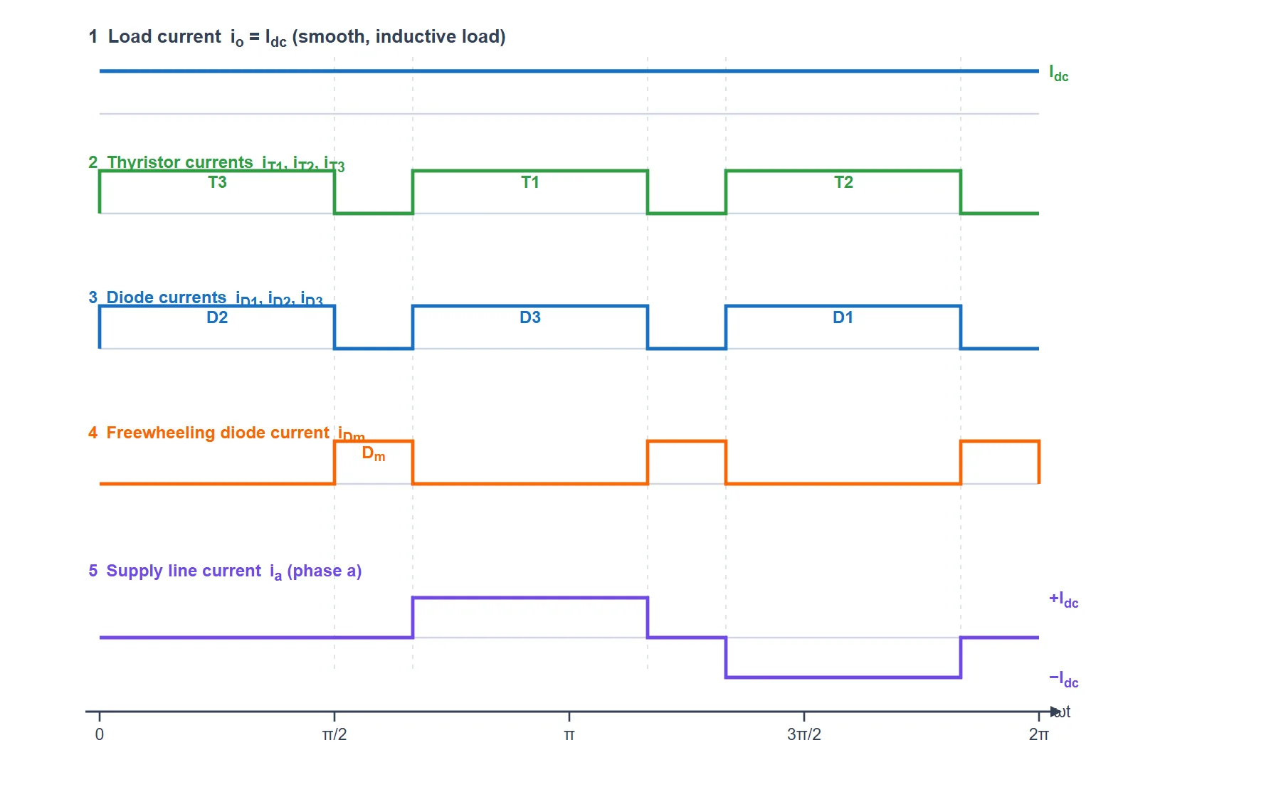
These currents are drawn for α = 90° with a highly inductive load, so the load current is smooth and almost constant at Idc. Because the current is steady, each device simply carries Idc in rectangular blocks while it conducts, which makes the sharing between thyristors, diodes and the freewheeling diode easy to see. The light dashed guides mark the 30° freewheeling instants.
Reading the Current Waveforms
- Load current io: with an inductive load the current is smooth and flat at Idc. It never falls to zero, even during the freewheeling gaps — the freewheeling diode keeps it flowing.
- Thyristor currents iT1, iT2, iT3: each thyristor carries Idc as a block. At α=90° that block is only 90° wide (not 120°), because 30° of its turn is handed to the freewheeling diode.
- Diode currents iD1, iD2, iD3: the bottom diodes conduct in the same way — 90° blocks — each paired with a thyristor to complete the load path.
- Freewheeling diode iDm: three short 30° pulses per cycle. Each pulse is exactly the gap where the output voltage sits at zero. Here the whole load current flows through Dm and the supply is momentarily disconnected. (For α ≤ 60° this current is zero — no freewheeling.)
- Supply line current ia: phase a carries +Idc while its thyristor conducts and −Idc while its diode conducts, and zero the rest of the time. This non-sinusoidal line current is why phase-controlled converters inject harmonics into the supply.
Average Output Voltage & Control Curve
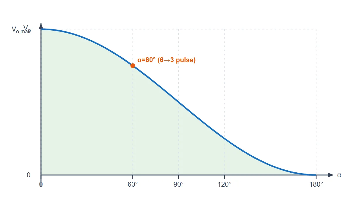
Whatever the firing angle, the average DC output of a three-phase semi-converter follows one neat formula (Vm is the peak phase voltage; VmL = √3 Vm is the peak line-to-line voltage):
It is largest at α = 0° and falls smoothly to zero at α = 180°. The curve below is that relationship, drawn as Vo against α (normalised to its maximum). Because it never crosses below zero, the whole control range lives in a single quadrant.
| Quantity | Formula & Value |
|---|---|
| Average output voltage | Vo = (3√3 Vm/2π)(1 + cosα) |
| Maximum output (α = 0°) | Vo = 3√3 Vm/π ≈ 1.654 Vm |
| Minimum output (α = 180°) | Vo = 0 |
| Output nature | 6-pulse for α ≤ 60°, 3-pulse for α > 60° |
| Ripple frequency | 6f (α≤60°) → 3f (α>60°) |
| Quadrant of operation | One quadrant (+V, +I — rectifying only) |
| Devices | 3 thyristors + 3 diodes (+ freewheeling diode) |
Effect of the Firing Angle α
The firing angle is the single control knob. A few points from Vo = (3√3 Vm/2π)(1 + cosα):
| Firing angle α | Average output Vo |
|---|---|
| 0° | 1.654 Vm (maximum, 6-pulse) |
| 30° | ≈ 1.543 Vm (6-pulse) |
| 60° | ≈ 1.240 Vm (boundary) |
| 90° | ≈ 0.827 Vm (3-pulse, freewheeling) |
| 120° | ≈ 0.414 Vm (3-pulse) |
| 180° | 0 (minimum) |
No matter how large α gets, the output cannot go negative, so the three-phase semi-converter can never invert or send energy back to the mains — it is strictly a one-quadrant controlled rectifier.
Semi-Converter vs Full-Converter (3-Phase)
| Parameter | 3-Phase Semi-Converter | 3-Phase Full-Converter |
|---|---|---|
| Devices | 3 thyristors + 3 diodes | 6 thyristors |
| Average output | Vo = (3√3 Vm/2π)(1 + cosα) | Vo = (3√3 Vm/π)cosα |
| Output polarity | Always positive (0 → +) | Positive or negative |
| Quadrants | One (rectifier only) | Two (rectifier + inverter) |
| Energy feedback | Not possible | Possible (inversion) |
| Freewheeling | Built in (diode Dm) | None |
| Input power factor | Better (same α) | Lower |
| Cost & control | Lower — only 3 gate circuits | Higher — 6 gate circuits |
Advantages & Disadvantages
Advantages
- Lower cost: three diodes replace three thyristors, so half the gate-drive and control circuitry is gone.
- Better input power factor than a full converter at the same firing angle, thanks to freewheeling.
- Simpler, more reliable control — only three thyristors to fire.
- Smooth DC control from maximum down to zero by adjusting α.
Disadvantages
- One-quadrant only: the output cannot reverse, so no inversion and no regenerative braking.
- More output ripple above 60° as it drops from 6-pulse to 3-pulse operation.
- Non-sinusoidal line current injects harmonics into the supply.
- Not suitable for drives that must brake by returning energy to the mains.
Applications
- Medium-power DC motor drives that only run in one direction — fans, pumps, conveyors, blowers.
- Battery charging and adjustable regulated DC power supplies.
- Electroplating, anodizing and electrolysis lines needing controllable DC current.
- Industrial heating and other resistive DC loads where output is controlled in one direction only.