Thevenin’s Theorem: Turning complex circuits into simple voltage sources.
- Introduction
- What is Thevenin’s Theorem?
- Thevenin’s Theorem Statement
- Why Use Thevenin’s Theorem?
- Steps to Apply Thevenin’s Theorem:
- Types of Nodes
- Nodal analysis with current source:
- Nodal analysis with voltage source:
- Nodal Analysis Vs Mesh Analysis
- Advantages of Nodal Analysis
- Disadvantages of Nodal Analysis
- Conclusion Of Nodal Analysis
- Applications of Nodal Analysis
- Nodal Analysis FAQs
Introduction
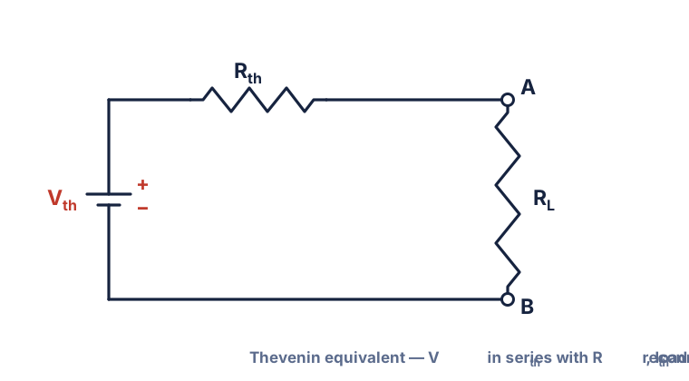
Any linear, bilateral two-terminal electrical network made up of voltage sources, current sources, and resistors can be replaced by a single voltage source (Vth) in series with a single resistor (Rth). This equivalent circuit behaves the same as the original from the load’s perspective and makes it easier to analyze circuit behavior with different loads. Thevenin’s Theorem is a key tool for simplifying complex circuits into a simple form for easier calculation of current, voltage, or resistance.
What is Nodal Analysis?
Thevenin’s Theorem states that any linear, bilateral two-terminal circuit can be replaced by an equivalent circuit with a single voltage source in series with a single resistor. This simplified version behaves exactly like the original circuit from the load’s perspective, making it much easier to analyze and calculate circuit behavior. Thevenin’s Theorem is a fundamental tool for reducing complex circuits to a simple form for easier analysis.
Thevenin’s Theorem Statement
"Any linear two-terminal electrical network consisting of voltage sources, current sources, and resistors can be replaced by an equivalent circuit consisting of a single voltage source (VTh) in series with a resistance (RTh), connected to the load."
It states that, "Any two terminal linear bilateral network containing a number of voltage sources and resistances can be replaced by an equivalent circuit consisting of a voltage source (Vth) in series with a resistance Rth." And RL is the load resistance.
Where:
- Vth = Open circuit voltage (VOC) between terminals A and B. It is also called Thevenin’s voltage.
- Rth = The equivalent resistance of the network as seen from the two terminals A and B with all other voltage sources replaced by their internal resistances. It is also called Thevenin’s resistance.
- RL = Any load resistance
Why Use Thevenin’s Theorem?
Steps to Apply Thevenin’s Theorem:
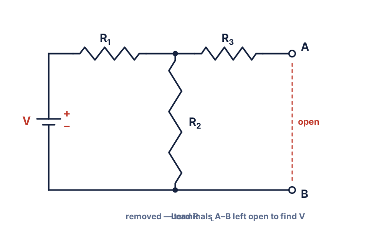
- Remove the load resistor (RL) from the circuit.
- Find VTh (Thevenin Voltage):o This is the open-circuit voltage across the terminals where the load was connected.
- Find RTh (Thevenin Resistance):
- Method 1:Deactivate all independent voltage sources (replace with short circuit) and current sources (replace with open circuit), then calculate equivalent resistance across the terminals.
- Method 2:Use source transformation, mesh/nodal analysis if needed.
- Draw the Thevenin Equivalent Circuit:
- A single voltage source VTh in series with resistance RTh.
- Reconnect the Load Resistor (RL) to this new equivalent circuit.
Thevenin's Theorem Explanation
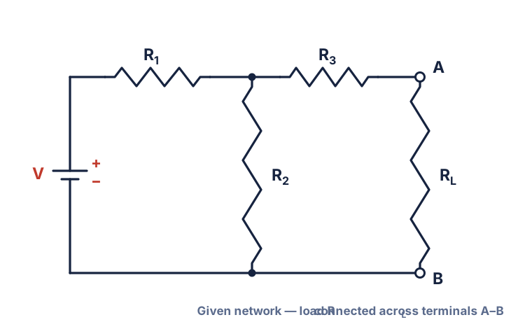
Circuit: To understand how Thevenin’s theorem is used and to determine the current flowing through any load resistor, you can follow a series of steps using the given circuit diagram. These steps will guide you through the process of simplifying the network and finding the desired current across the load.
Nodal analysis with current source:
When doing nodal analysis on a circuit with a current source you need to include the current source in the node voltage equations.
1. Find the Current Source : Where is the current source connected to? Unlike voltage sources, current sources don’t affect the node voltages but affect the current into or out of the node.
2. KCL Equations : When writing KCL equations for nodes connected to a current source, include the current source in the equation. The current source is part of the total current into or out of the node.
3. Look to the Direction : Look at the current source direction. If it’s coming into the node, the current source term in the KCL equation will be positive, if it’s leaving the node, it will be negative.
4. Solve the Equations : Now solve the KCL equations with the current sources. Use matrices or software to do this easily.
By including the current source in the nodal analysis equations, you can analyze circuits with current sources and other components.
Nodal analysis with voltage source:
When you’re doing nodal analysis on a circuit that includes voltage sources, you need to account for how those sources affect the voltages at the nodes. Here’s a clear, original guide for handling voltage sources in nodal analysis:
1. Include Voltage Sources in Your Setup:
When you write your nodal equations, treat voltage sources differently from current sources. Voltage sources directly set the voltage difference between two nodes, so you must include them in your equations.
2. Watch the Polarity:
Pay close attention to which way each voltage source is connected. If a voltage source goes from a node
to ground, the voltage at that node is equal to the source’s value (with the correct sign for polarity).
If the voltage source connects between two non-reference nodes, you’ll need to write an equation that
relates those two node voltages based on the source’s polarity.
3. Add Voltage Source Terms to Your Equations:
When you set up your equations for each node, make sure to include the effect of any voltage sources. If a voltage source is between a node and ground, set the node voltage equal to the source value. If it’s between two nodes, write an equation that shows the voltage difference between those nodes equals the source voltage.
4. Solve the System of Equations:
Once you’ve included all the voltage source effects, solve the system of equations—by hand for simple circuits, or with a calculator or software for more complex ones. This will give you the voltages at each node.
By following these steps and making sure you properly include voltage sources in your nodal equations, you’ll get accurate node voltages for any circuit.
Nodal Analysis Vs Mesh Analysis:
| Nodal Analysis | Mesh Analysis |
|---|---|
| Analysis is done by focusing on the circuit’s nodes. | Analysis is performed using loops in the circuit. |
| Relies mainly on applying Kirchhoff’s Current Law (KCL). | Relies mainly on applying Kirchhoff’s Voltage Law (KVL). |
| Node voltages are calculated to determine other values. | Mesh currents are calculated to determine other values. |
| Suitable for all types of circuits, whether planar or not. | Suitable only for circuits without crossing connections (planar). |
| More effective when the circuit has several voltage sources. | More effective when the circuit has several current sources. |
Super Node Analysis
Supernode in Nodal Analysis
A supernode is a special case in nodal analysis that occurs when a voltage source connects two non-reference nodes. In this situation, the two nodes and the voltage source are treated together as a single unit called a supernode. To analyze a supernode, both Kirchhoff’s Current Law (KCL) and Kirchhoff’s Voltage Law (KVL) are used. The process is similar to regular nodal analysis, but you combine the current equations for the involved nodes and also write an equation for the voltage source connecting them. This helps in solving for the unknown node voltages.
Properties of a Supernode:
- A supernode does not have a single, well-defined voltage of its own.
- Both KCL and KVL must be applied to solve the circuit equations involving a supernode.
- The voltage difference between the two nodes forming the supernode is set by the voltage source connecting them.
| Node | Supernode |
|---|---|
| A node is a point in a circuit where two or more circuit elements meet. Every junction where branches connect is considered a node. | A supernode is formed when a voltage source connects two non-reference nodes. The two nodes and the voltage source are treated as a single, combined node for analysis. |
| Each node (except the reference) has its own voltage variable. | A supernode does not have its own voltage; instead, the voltage difference between the two nodes is set by the voltage source. |
| KCL (Kirchhoff’s Current Law) is applied directly at each node. | For a supernode, KCL is applied to the entire supernode, and KVL (Kirchhoff’s Voltage Law) is used to relate the node voltages across the voltage source. |
| Used for general nodal analysis in any circuit. | Used as a special case in nodal analysis when a voltage source is present between two non-reference nodes. |
- A supernode is a special case in nodal analysis that occurs when a voltage source is connected between two non-reference (non-ground) nodes in a circuit. In this situation, these two nodes and the voltage source are treated together as a single entity called a supernode.
- To analyze a supernode, you apply both Kirchhoff’s Current Law (KCL) and Kirchhoff’s Voltage Law (KVL). The process is similar to regular nodal analysis, but when you reach the supernode, you combine the current equations for the involved nodes and use the voltage source equation (from KVL) to relate the voltages at those nodes. This approach provides all the necessary equations to solve for the unknown node voltages. >
Properties of a Supernode:
- A supernode does not have a single, well-defined voltage of its own.
- Both KCL and KVL must be applied to solve the equations involving a supernode.
- The voltage difference between the two nodes forming the supernode is set by the voltage source connected between them.
Advantages of Nodal Analysis
- Straightforward and Systematic: Nodal analysis offers a clear, step-by-step approach that makes it easier to solve even complex circuits. By focusing on node voltages, it simplifies the process of setting up and solving equations.
- Efficient for Large Circuits: This method is especially useful for circuits with many components and nodes, as it reduces the number of equations needed compared to other techniques like mesh analysis.
- Works for Planar and Non-Planar Circuits: Nodal analysis can be applied to both planar and non-planar networks, making it versatile for different circuit layouts.
- Applicable to AC and DC Circuits: You can use nodal analysis for both alternating current (AC) and direct current (DC) circuits without changing the basic process.
- Handles Multiple Sources and Components: The method is well-suited for circuits with several voltage and current sources, as well as mixed components like resistors, capacitors, and inductors.
- Foundation for Computer-Aided Analysis: Nodal analysis forms the basis for many circuit simulation tools (such as SPICE), allowing for quick and accurate analysis of large and complex networks.
- Direct Calculation of Node Voltages: By focusing on node voltages, it allows you to easily determine the voltage at any point in the circuit, which can then be used to find currents and power as needed.
Disadvantages of Nodal Analysis
- Nodal analysis assumes all circuit elements behave linearly, so it struggles with nonlinear components like diodes or transistors.
- It can be challenging to handle dependent sources because their values depend on other circuit variables, requiring extra equations or adjustments.
- For circuits with many nodes, the number of simultaneous equations can become very large, making manual solving impractical.
- Choosing incorrect nodes or reference points can lead to errors in the analysis.
- Compared to mesh analysis, nodal analysis may result in more equations since circuits often have more nodes than meshes.
Applications of Nodal Analysis
- Solving Complex Circuits: Nodal analysis is used to find voltages at different points in circuits with many nodes and branches.
- Circuit Design and Optimization: Engineers use this method to design, test, and improve circuits for better efficiency and reliability.
- Power and Control Systems: It helps analyze and optimize power distribution networks and control systems.
- Simulation Software: Many circuit simulators, such as SPICE, use nodal analysis as a core algorithm.
- Specialized Applications: Nodal analysis is also useful in operational amplifier design, digital-to-analog converters, and measuring unknown resistances.
- Signal Processing: It is essential in designing filters and amplifiers in electronic systems.
Conclusion Of Nodal Analysis
In summary, nodal analysis is a powerful and systematic method for analyzing complex electrical circuits by focusing on node voltages. By applying Kirchhoff’s Current Law, Kirchhoff’s Voltage Law, and Ohm’s Law, it allows engineers to form and solve equations for a wide variety of circuits. The concept of a supernode is especially useful when voltage sources connect two non-reference nodes. Nodal analysis is valuable in circuit design, optimization, and in the study of power and control systems. Its flexibility makes it suitable for both AC and DC circuits, as well as planar and non-planar networks. While it can be challenging to apply to non-linear circuits, nodal analysis remains a fundamental and widely used tool in electrical engineering.
Nodal Analysis FAQs
Nodal analysis is most useful for analyzing complex circuits with multiple nodes and branches.
ΣI = 0
The first step is to identify all nodes and select a reference node.