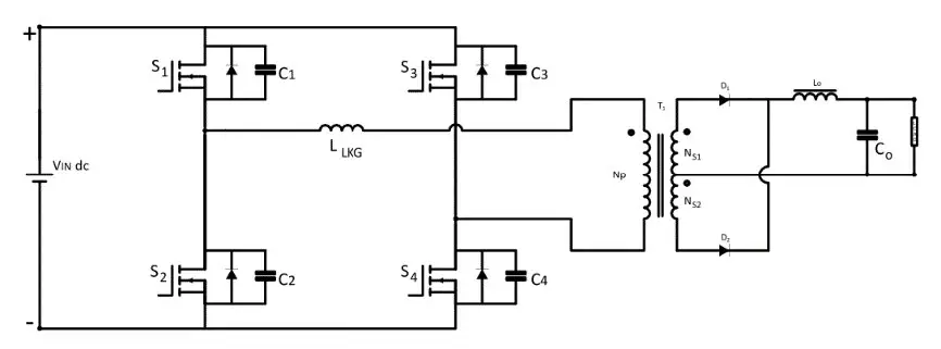
What is a phase-shifted full-bridge converter?
The phase-shifted full-bridge (PSFB) is the standard high-power, soft-switching isolated DC-DC converter. It uses the same four-switch H-bridge as a hard-switched full-bridge, but instead of pulse-width modulation both legs switch at a fixed 50% duty and the output is controlled by the phase shift φ between the two legs. Crucially, the transformer leakage inductance resonates with each MOSFET's output capacitance Coss during the switching transitions to drive the drain voltage to zero before turn-on — zero-voltage switching (ZVS) — eliminating capacitive turn-on losses and allowing high frequency with high efficiency and low EMI.
How phase-shift control works
Call one leg the leading leg and the other the lagging leg. The overlap between their 50%-duty square waves determines how long the full ±Vs is applied to the transformer. Increasing the phase shift φ increases that overlap and the output. The effective duty is D_eff = φ/360 (φ from 0° to 180°), and:
This simulator numerically integrates the real PSFB output stage — the phase-controlled ±Vs drive, the leakage-induced duty loss, the magnetizing current and the output LC — to steady state, then compares the measured Vo to the equation above (validated at zero leakage / ideal devices) in the accuracy panel.
Zero-voltage switching (ZVS) & the two legs (topic-specific)
Each leg turns on only after resonance has swung its switch-node voltage to zero. The energy available is the inductive energy at the transition, ½·L·I²; the energy required is what it takes to charge and discharge the two MOSFET output capacitances, ≈ Coss·Vs².
- Leading leg: transitions while carrying the full reflected load current plus the magnetizing current, so it has plenty of energy — ZVS almost always succeeds.
- Lagging leg: transitions relying only on the leakage-stored energy, which falls with load. At light load
½·Llk·I²drops belowCoss·Vs²and the lagging leg loses ZVS — the classic PSFB limitation.
The ZVS window analyzer above shows the energy balance and pass/fail for each leg live — drop the load and watch the lagging leg fall out of ZVS.
Duty loss — the price of the leakage inductance
The same leakage inductance that enables ZVS also causes duty loss: at each commutation the primary current must slew from one polarity to the other through Llk before the output rectifier can conduct, and during that slew no voltage reaches the output. The effective duty is therefore less than φ/360, by roughly ΔD ≈ 4·Llk·fsw·n·Io/Vs. Larger leakage gives easier ZVS but more duty loss — the central PSFB design trade-off, shown live here.
Advanced options in this simulator
- Phase-shift control: set the output with φ at fixed frequency, the way a real PSFB is regulated.
- ZVS window analyzer: leading/lagging-leg energy balance and pass/fail, with Coss and Llk controls.
- Leakage duty loss: watch Vo droop as leakage or load rises.
- Device model: MOSFET Rds(on), diode Vf, inductor DCR and capacitor ESR; the accuracy check stays locked to the ideal Vo.
- Ripple spectrum & export: FFT at twice fsw, plus CSV/report/PNG.
The six isolated DC-DC converters
| Converter | Switches | Ideal Vo | Switching |
|---|---|---|---|
| Flyback | 1 | n·Vs·D/(1−D) | Hard |
| Forward | 1 | n·Vs·D | Hard |
| Push-Pull | 2 (center-tap) | 2·n·Vs·D | Hard |
| Half-Bridge | 2 + split caps | n·Vs·D | Hard |
| Full-Bridge | 4 | 2·n·Vs·D | Hard |
| Phase-Shifted FB | 4 | 2·n·Vs·Deff | ZVS (soft) |
Explore the others: Flyback, Forward, Push-Pull, Half-Bridge and Full-Bridge simulators. For the full theory see the Phase-Shifted Full-Bridge tutorial.
Applications
High-power isolated conversion where efficiency matters: EV and battery chargers, telecom and server rectifiers, welding supplies and industrial power from roughly 500 W to several kW.
Frequently asked questions
How is a PSFB converter controlled?
Both legs run at fixed 50% duty; the phase shift φ between them sets the output: Vo = 2·n·Vs·D_eff with D_eff = φ/360. Fixed-frequency phase-shift control enables ZVS.
What is ZVS?
Turning each MOSFET on only after resonance has driven its drain voltage to zero, so there is no capacitive turn-on loss. It needs ½·L·I² ≥ Coss·Vs² at the transition.
Why does the lagging leg lose ZVS at light load?
It relies only on leakage-stored energy, which falls with load. At light load ½·Llk·I² drops below Coss·Vs² and ZVS is lost — the analyzer shows this.
What is duty loss?
Time lost each commutation while the primary current slews through the leakage inductance before the rectifier conducts: ΔD ≈ 4·Llk·fsw·n·Io/Vs. It lowers Vo below 2·n·Vs·D_eff.
Why use a PSFB over a hard-switched full-bridge?
Same power stage, but ZVS eliminates capacitive turn-on losses, so it runs at higher frequency with higher efficiency and lower EMI — ideal above ~500 W.