Vienna Rectifier
A three-phase, three-level boost PFC rectifier that draws clean sinusoidal currents from all three lines using just three switches — and halves the voltage stress on its devices by splitting the DC bus in two.
- Introduction
- What is a Vienna Rectifier?
- Circuit Diagram & Construction
- The Three-Level Idea (Why It Matters)
- Modes of Operation
- Line-Cycle Waveforms (Deep Dive)
- Switching-Cycle Waveforms (Deep Dive)
- Control Scheme
- Vienna vs Other Three-Phase Rectifiers
- Key Parameters & Formulas
- Advantages & Disadvantages
- Applications
- Frequently Asked Questions – FAQs
- Related Topics
Introduction
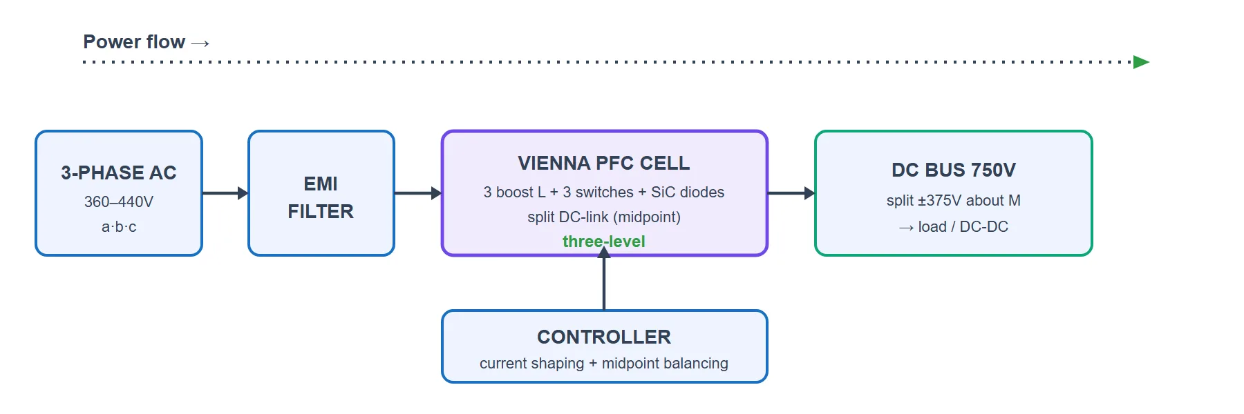
When you need to pull a few kilowatts (or tens of kilowatts) from a three-phase mains and turn it into a clean DC bus — think EV fast chargers, telecom and server power, big industrial supplies — you want three things at once: a near-unity power factor, low harmonics, and high efficiency. The Vienna rectifier delivers all three with a surprisingly lean circuit: it corrects the power factor on all three phases using only three switches.
What makes it special is that it is a three-level converter. Instead of chopping the full DC-bus voltage, each phase can be connected to the top rail, the bottom rail, or a midpoint in between — so every switching step only moves half the bus voltage. That halves the voltage stress on the devices, shrinks the input filter and lifts efficiency. A representative 3-phase design takes a 360–440 V three-phase input and produces a 750 V DC bus at 5 kW with about 98.7% efficiency, using SiC boost diodes and 650 V MOSFETs. This page walks through the circuit, the three-level idea, the modes of operation and the full waveforms.
What is a Vienna Rectifier?
A Vienna rectifier is a three-phase, three-level, three-switch boost-type power-factor-correction rectifier. It takes three-phase AC in and produces a regulated DC bus out, while forcing each input current to be a clean sine wave in phase with its voltage. It is unidirectional — power flows only from the AC side to the DC side (it cannot feed energy back to the grid), which is exactly what a charger or power supply needs.
The name comes from the university where it was developed (TU Wien). Its defining features are:
- Three-level output — each phase can sit at the positive rail, the negative rail, or the DC midpoint (neutral), so switching only ever swings half the bus voltage.
- Only three active switches — one bidirectional switch per phase, versus six in a full active front-end.
- Boost operation in CCM — the output DC voltage is always higher than the peak line-to-line input, and the inductor current stays continuous for low ripple.
- Lower device voltage rating — switches and diodes only block about half the DC bus, so cheaper, faster devices can be used.
Circuit Diagram & Construction
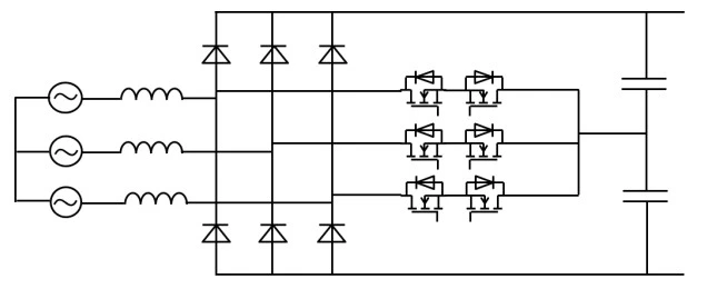
The Vienna rectifier is built from three identical phase legs sharing one split DC bus. Per phase you have:
- A boost inductor (L) — in series with the line; it stores energy and shapes the phase current into a sine.
- Two boost diodes (D+ and D−) — fast SiC diodes that connect the phase node up to the positive rail and down to the negative rail. With three phases that is six diodes in total.
- One bidirectional switch (S) — connects the phase node to the DC midpoint M. Because the line current is AC, this switch must carry current both ways, so it is built from two MOSFETs back-to-back (or one MOSFET inside a small diode bridge). Three phases → three switches.
- A split DC-link (C1 and C2) — two series capacitors across the output; their joint is the midpoint M, sitting at half the bus voltage.
The Three-Level Idea (Why It Matters)
In a plain two-level rectifier each phase can only be pulled to the top rail or the bottom rail — a full swing of the whole DC voltage every time it switches. The Vienna rectifier adds a third option: the midpoint M. So each phase node P can sit at one of three voltages relative to M:
Because each switching step now moves only half the bus voltage, three good things follow: the devices only have to block Vdc/2 (so lower-voltage, faster, cheaper switches work), the voltage the inductor sees changes in smaller steps (so the input current is smoother and the EMI filter shrinks), and switching losses drop. This is why the Vienna rectifier is a favourite for efficient three-phase front-ends.
Modes of Operation
Every phase behaves the same way, so we can understand the whole converter by looking at one phase leg. What the phase node P connects to depends on just two things: whether its switch S is ON or OFF, and the direction of that phase’s current. That gives four states:
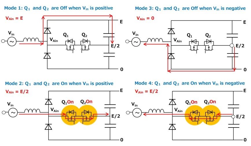
- (a) & (b) Switch ON → the 0 level: the bidirectional switch shorts the phase node to the midpoint M, so P sits at 0. The switch conducts whichever way the current flows — that is exactly why it has to be bidirectional. During this time the phase inductor is charging.
- (c) Switch OFF, current positive → +Vdc/2: the top boost diode D+ conducts, pushing the inductor current up into the top capacitor C1. The node is clamped to the positive rail.
- (d) Switch OFF, current negative → −Vdc/2: the bottom boost diode D− conducts, drawing current up from the bottom capacitor C2. The node is clamped to the negative rail.
- The result: by turning the switch on and off quickly (PWM) while the current is positive, the phase is chopped between 0 and +Vdc/2; while the current is negative it is chopped between 0 and −Vdc/2. Averaged over each switching cycle, the node voltage follows the sine of the input — and the current comes out sinusoidal.
Line-Cycle Waveforms (Deep Dive)
Over one mains cycle you can see all three phases work together. The three input currents come out as clean sines, each in step with its own voltage and 120° apart, and the phase-to-midpoint voltage shows the tell-tale three-level staircase.
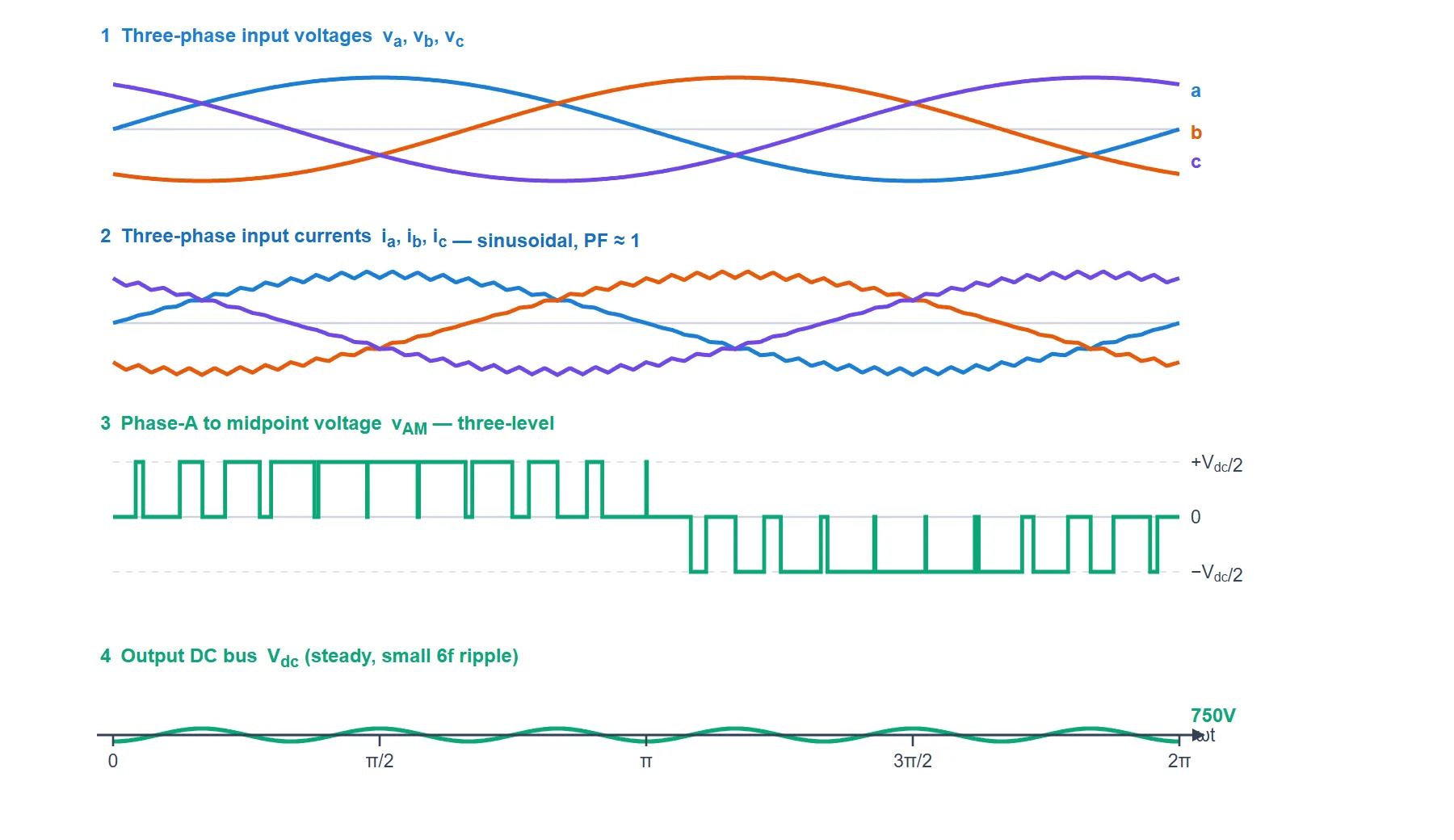
- Input currents: three smooth sines, each locked in phase with its own voltage, so the power factor is near unity and the harmonics are low.
- Three-level voltage vAM: notice it never jumps the full bus — it only ever steps between an outer rail and the midpoint. The pulses are wide near the voltage peak (high duty) and narrow near the zero-crossing, which is what shapes the sinusoidal current.
- Output Vdc: because three phases deliver power in turn, the natural output ripple is small and at six times the line frequency, so the DC bus is very steady.
Switching-Cycle Waveforms (Deep Dive)
Zooming into a few switching periods within the positive half of one phase, the leg behaves like a boost converter that toggles the phase between the midpoint (0) and the top rail (+Vdc/2):
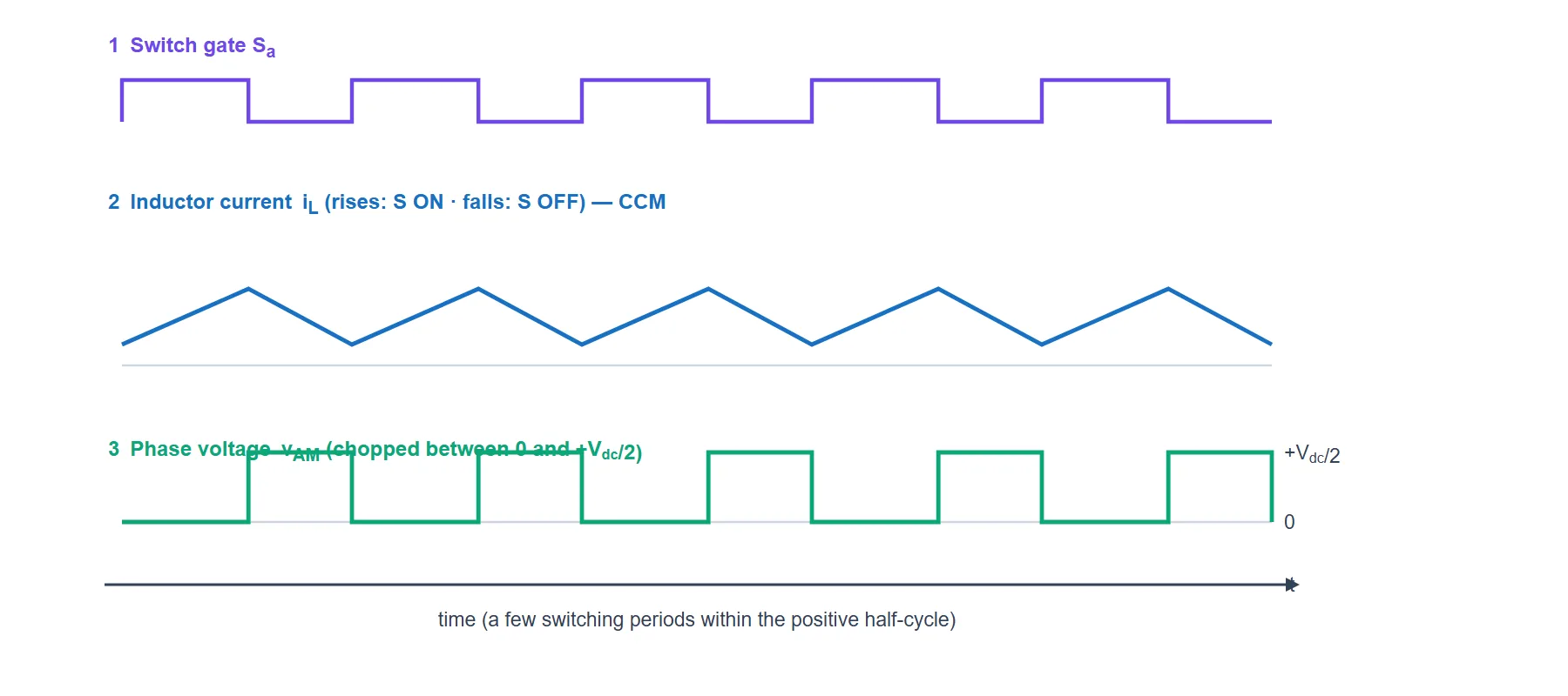
- Inductor current iL: a triangular ripple that rises while the switch is on and falls while it is off. In continuous conduction mode it never touches zero, so peak and RMS currents stay low.
- Duty ratio: the fraction of each period the switch is ON sets how much the current ramps. The controller varies it slowly across the line cycle so the average current tracks the sine of the phase voltage.
- Two-level chopping (within a half): in the positive half the phase only ever swings between 0 and +Vdc/2 — half the bus — which is the whole point of the three-level structure.
Control Scheme
A Vienna rectifier is run with the usual cascaded PFC control, plus one extra job unique to the split bus:
- Outer voltage loop: a slow PI regulator holds the total DC bus at its target (750 V here) and decides how much current the converter should draw.
- Inner current loops: force each phase current to follow a sine reference in phase with its voltage, giving near-unity power factor and low THD. Each phase’s switch duty is set every switching cycle.
- Midpoint (neutral-point) balancing: the two DC-link capacitors must stay at equal voltage. If they drift apart, the controller nudges the switching to steer a little extra current into or out of the midpoint and re-balances them — a control task that only three-level converters have.
Vienna vs Other Three-Phase Rectifiers
| Feature | 6-Pulse Diode Bridge | 2-Level Active Front-End | Vienna Rectifier |
|---|---|---|---|
| Power factor / THD | Poor (no PFC) | Excellent | Excellent |
| Active switches | 0 | 6 | 3 |
| Levels | — | 2 | 3 |
| Device voltage stress | Full bus | Full bus | Half bus (Vdc/2) |
| Power direction | Unidirectional | Bidirectional | Unidirectional |
| Control complexity | None | High | Moderate (+ midpoint balance) |
| Best for | Cheap, dirty loads | Regen / motor drives | Efficient chargers & supplies |
Key Parameters & Formulas
| Quantity | Formula & Value |
|---|---|
| Boost condition (must hold) | Vdc > √2 · VLL (above the line-to-line peak) |
| Switch voltage stress | Vdc / 2 (half the bus — the three-level benefit) |
| Output levels per phase | +Vdc/2, 0, −Vdc/2 |
| Active switches | 3 (one bidirectional switch per phase) |
| Boost diodes | 6 (two SiC diodes per phase) |
| Output ripple frequency | 6f (300 Hz on a 50 Hz grid) |
| Example design (typical 5 kW) | 400V in → 750V out, 5 kW, ≈98.7% |
Advantages & Disadvantages
Advantages
- Only three switches for full three-phase PFC — fewer parts and gate drivers than a six-switch front-end.
- Half the voltage stress — three-level operation lets you use lower-voltage, faster, cheaper devices.
- High efficiency and power density — smaller switching steps mean lower losses and a smaller input filter.
- Clean sinusoidal input currents — near-unity power factor and low THD on all three phases.
Disadvantages
- Unidirectional only — it cannot return power to the grid, so it is not suitable for regenerative drives.
- Bidirectional switches — each switch needs two MOSFETs (or a MOSFET plus a diode bridge), adding device count per leg.
- Midpoint balancing — the split DC-link needs active balancing, adding a control task.
- Boost only — the output must always be above the line-to-line peak; it cannot step the voltage down.
Applications
- EV fast chargers — the three-phase PFC front-end ahead of the isolated DC-DC stage.
- Telecom and server / data-centre power chasing very high efficiency.
- Industrial power supplies and welding sets.
- Wind and aircraft power systems and other high-power three-phase rectification.