Complete Mesh Analysis Mastery Guide
Master mesh current analysis from basic principles to advanced applications - solve complex circuits with confidence using systematic loop equations and KVL
Complete Learning Path - Mesh Analysis Fundamentals to Applications
Navigate through comprehensive coverage of Mesh Analysis from basic principles to advanced applications
What is Mesh Analysis?
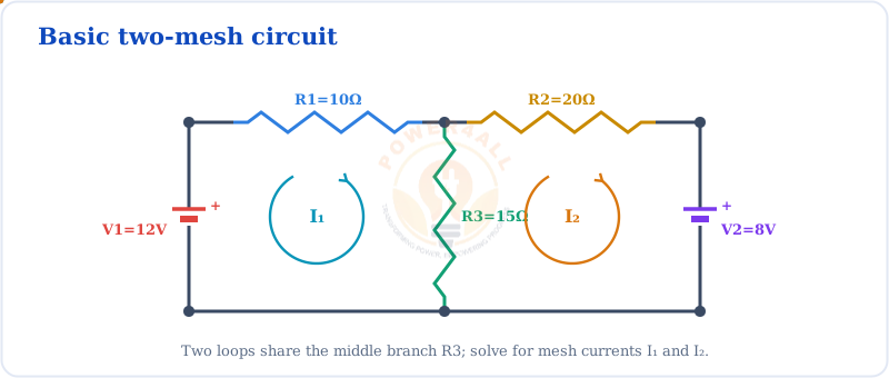
Mesh analysis is a systematic method for analyzing electrical circuits by applying Kirchhoff's Voltage Law (KVL) to independent loops or "meshes" in a circuit. This powerful technique allows engineers to determine unknown currents by solving a set of linear equations, making complex circuit analysis manageable and efficient.
Reference: Circuit diagram and concept adapted from GeeksforGeeks - Mesh Analysis
Basic Two-Mesh Circuit
The Water Pipe Network Analogy
Think of mesh analysis like analyzing water flow in a network of connected pipes with loops. Each loop (mesh) has water circulating through it, and we can calculate these circulation patterns by applying pressure balance equations around each loop.
Perfect Comparison
- Water circulation in loops → Current circulation in meshes
- Pressure balance around loops → Voltage balance (KVL)
- Pipe restrictions → Resistances in branches
- Pressure sources → Voltage sources
∑V = 0 (around each mesh)
Kirchhoff's Voltage Law applied to each independent loop
Key Definitions and Terms
Mesh (Loop)
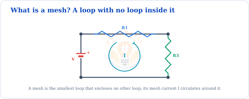
A closed path in a circuit that doesn't contain any other closed paths within it. It's the smallest possible loop that can be identified in a planar circuit.
Mesh Current
A hypothetical current assigned to each mesh that flows around the entire loop. These currents may not correspond to actual branch currents.
Planar Circuit
A circuit that can be drawn on a flat surface without any wires crossing each other. Mesh analysis is only applicable to planar circuits.
Independent Meshes
The minimum number of meshes needed to analyze a circuit completely. For a circuit with 'n' nodes and 'b' branches: meshes = b - n + 1
When to Use Mesh Analysis
Ideal Situations
- Planar circuits: Can be drawn without crossing wires
- Voltage sources: More voltage sources than current sources
- Multiple loops: Complex networks with many interconnected loops
- Current calculation: When you need to find currents in branches
- Systematic approach: When you want a methodical solution process
Avoid When
- Non-planar circuits: Wires must cross each other
- Many current sources: Leads to supermesh complications
- Node voltage needed: When voltages at nodes are primary concern
- Simple circuits: Basic series/parallel can be solved more easily
- High node count: Nodal analysis might be more efficient
Real-World Mesh Analysis Applications
- Power system analysis: Distribution network current flow
- Electronic circuit design: Amplifier and filter circuits
- Control system analysis: Feedback loop behavior
- Motor drive circuits: Current control in motor controllers
- Power supply design: Regulation and filtering circuits
- Analog circuit analysis: Op-amp and transistor circuits
Historical Context
Mesh analysis was developed as one of the fundamental circuit analysis techniques alongside nodal analysis. It's based on Kirchhoff's Voltage Law, discovered by Gustav Kirchhoff in 1845. The method provides a systematic approach that's particularly well-suited for computer-aided circuit analysis and is the foundation for many circuit simulation programs.
Mesh Analysis Fundamentals
Understanding the theoretical foundation of mesh analysis is crucial for applying it correctly. This section covers the underlying principles, mathematical relationships, and the systematic approach that makes mesh analysis such a powerful tool for circuit analysis.
Reference: KVL application concept from BYJU'S - Mesh Analysis
KVL Applied to Mesh
Kirchhoff's Voltage Law (KVL) Foundation
The Mathematical Basis of Mesh Analysis
Mesh analysis is built entirely on Kirchhoff's Voltage Law, which states that the algebraic sum of all voltage drops around any closed loop in a circuit equals zero. This fundamental principle ensures energy conservation in electrical circuits.
∑ᵢ Vᵢ = 0
Sum of all voltage drops around a closed loop equals zero
Sign Convention Rules
| Element Type | Voltage Expression | Sign Convention | Example |
|---|---|---|---|
| Resistor (own mesh) | +I × R | Positive (voltage drop) | +I₁ × R₁ |
| Resistor (shared) | +(I₁ - I₂) × R | Algebraic difference | +(I₁ - I₂) × R₃ |
| Voltage source (aiding) | +V | Positive (energy source) | +12V |
| Voltage source (opposing) | -V | Negative (opposes current) | -5V |
Circuit Requirements and Limitations
Planar Circuit Requirement
Essential condition for mesh analysis
What Makes a Circuit Planar?
- No wire crossings: All connections can be drawn without wires crossing
- Flat surface representation: Can be drawn on a 2D plane
- Clear mesh identification: Independent loops are easily identifiable
- Redrawing possibility: Sometimes non-planar appearance can be redrawn as planar
Testing for Planarity
- Try to redraw the circuit without crossing wires
- Use Kuratowski's theorem for formal testing
- Count: If E ≤ 3V - 6 (E=edges, V=vertices), likely planar
- Simple circuits with few loops are typically planar
Mesh Count Determination
Calculate number of independent meshes
M = B - N + 1
M = Meshes, B = Branches, N = Nodes
Alternative Formulas
- For planar circuits: M = L (number of loops)
- Window method: Count independent windows in circuit
- Matrix rank: Rank of fundamental loop matrix
Example Calculation
Circuit with 5 branches and 4 nodes:
- Meshes: M = 5 - 4 + 1 = 2
- Equations needed: 2 KVL equations
- Unknown currents: 2 mesh currents
Mesh Current vs Branch Current
Understanding the Relationship Between Different Current Types
Mesh currents are mathematical tools that simplify analysis. They don't always represent actual physical currents but provide a systematic way to find real branch currents.
Current Relationships
| Branch Location | Current Expression | Explanation | Example |
|---|---|---|---|
| Branch in single mesh | I_branch = I_mesh | Direct correspondence | I₁ = I_mesh1 |
| Branch shared by two meshes | I_branch = I_mesh1 - I_mesh2 | Algebraic difference | I₃ = I₁ - I₂ |
| Branch with current source | I_branch = I_source | Fixed by source | I₄ = 3A |
Branch Current Calculation Example
Given mesh currents I₁ = 2A (clockwise) and I₂ = 1.5A (clockwise):
- Branch only in mesh 1: I_branch = 2A
- Branch only in mesh 2: I_branch = 1.5A
- Branch shared (mesh 1 left to right, mesh 2 right to left): I_branch = 2 - 1.5 = 0.5A (left to right)
- Direction: Positive result means current flows in assumed direction
Step-by-Step Mesh Analysis Procedure
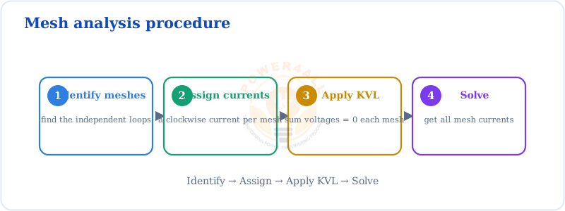
Mastering mesh analysis requires following a systematic, step-by-step approach. This methodical procedure ensures accuracy, reduces errors, and makes even complex circuits manageable. Follow these steps in order for consistent success.
Reference: Step-by-step procedure adapted from Testbook - Mesh Analysis
Systematic Mesh Analysis Procedure
Complete Systematic Approach
Detailed Step Explanations
Step 1: Circuit Preparation
Prepare the circuit for mesh analysis
Key Actions
- Check planarity: Verify no essential wire crossings
- Redraw if needed: Make circuit layout clear and organized
- Label all elements: Mark resistors, sources, and nodes clearly
- Identify mesh boundaries: Clearly see where each mesh begins and ends
Common Issue
Non-planar circuits cannot be analyzed with mesh analysis. If you cannot redraw without crossings, use nodal analysis instead.
Step 2: Mesh Identification
Identify and count independent meshes
Identification Process
- Look for windows: Each independent window is typically a mesh
- Avoid including smaller loops: Don't double-count nested loops
- Use systematic counting: Apply M = B - N + 1 formula
- Mark clearly: Number or label each identified mesh
Quick Verification
For a circuit with 6 branches and 4 nodes:
- Expected meshes: M = 6 - 4 + 1 = 3
- Check your count: Should identify exactly 3 meshes
- If different: Recheck branch and node counting
Step 3: Current Assignment
Assign mesh currents systematically
Assignment Rules
- Consistent direction: All clockwise or all counterclockwise
- Clear labeling: Use I₁, I₂, I₃ or similar systematic notation
- Arrow indication: Draw current arrows on the circuit diagram
- Reference direction: Remember these are assumed directions
Pro Tip
Clockwise is conventional, but the choice doesn't affect final answers. Negative results simply mean current flows opposite to assumed direction.
KVL Equation Writing Guidelines
How to Write Correct KVL Equations for Each Mesh
Writing correct KVL equations is the heart of mesh analysis. Follow these guidelines to ensure accuracy and avoid common mistakes.
Voltage Drop Conventions
| Element Type | Voltage Term | When Positive | When Negative |
|---|---|---|---|
| Resistor (single mesh) | I × R | Current flows with mesh direction | Never (always positive drop) |
| Resistor (shared) | (I₁ - I₂) × R | Net current flows with mesh direction | Net current flows against mesh direction |
| Voltage source | +V or -V | Source aids mesh current | Source opposes mesh current |
| Current source | Special handling | Use supermesh technique | Use supermesh technique |
Sample KVL Equation
For Mesh 1 with 10V source, 5Ω resistor, and shared 3Ω resistor:
- Voltage source: +10V (assuming it aids current)
- 5Ω resistor: -I₁ × 5Ω (voltage drop)
- Shared 3Ω resistor: -(I₁ - I₂) × 3Ω
- KVL equation: 10 - 5I₁ - 3(I₁ - I₂) = 0
- Simplified: 10 - 8I₁ + 3I₂ = 0
Solution Methods
Manual Solution Methods
Solve equations by hand
Substitution Method
- Solve one equation for one variable
- Substitute into other equations
- Good for 2-3 equations
- Step-by-step verification possible
Elimination Method
- Multiply equations to eliminate variables
- Add/subtract equations systematically
- Works well for larger systems
- Systematic and organized approach
Matrix Methods
Systematic approach for complex circuits
Matrix Equation Form
[R][I] = [V]
Resistance matrix × Current vector = Voltage vector
Solution Process
- Form resistance matrix [R]
- Create voltage vector [V]
- Solve: [I] = [R]⁻¹[V]
- Use calculator or computer
Solved Examples: Step-by-Step Solutions
Learning mesh analysis is best achieved through detailed examples. These step-by-step solutions demonstrate the complete process from circuit preparation to final verification, covering simple to complex scenarios you'll encounter in practice.
References: Example problems adapted from GeeksforGeeks, BYJU'S, and Testbook
Example 1: Two-Mesh Circuit (Source: GeeksforGeeks)
Problem Statement
Two-Mesh Circuit
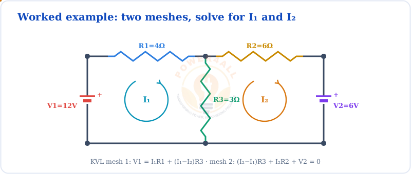
Given: Circuit with V₁ = 12V, V₂ = 6V, R₁ = 4Ω, R₂ = 6Ω, R₃ = 3Ω
Find: All mesh currents and branch currents
Complete Solution for Example 1
- Circuit has 2 clear meshes (left and right loops)
- Assign I₁ (left mesh, clockwise) and I₂ (right mesh, clockwise)
- R₃ is shared between both meshes
- Starting from voltage source, going clockwise:
- +12V - I₁R₁ - (I₁ - I₂)R₃ = 0
- 12 - 4I₁ - 3(I₁ - I₂) = 0
- Equation 1: 12 - 7I₁ + 3I₂ = 0
- Starting from shared resistor, going clockwise:
- +(I₂ - I₁)R₃ - I₂R₂ - 6V = 0
- 3(I₂ - I₁) - 6I₂ - 6 = 0
- Equation 2: -3I₁ - 3I₂ - 6 = 0
- Equation 1: 7I₁ - 3I₂ = 12
- Equation 2: 3I₁ + 3I₂ = -6
- Adding equations: 10I₁ = 6
- I₁ = 0.6A
- Substituting: 3(0.6) + 3I₂ = -6
- I₂ = -2.6A
- Through R₁: I_R1 = I₁ = 0.6A
- Through R₂: I_R2 = |I₂| = 2.6A (opposite to assumed direction)
- Through R₃: I_R3 = I₁ - I₂ = 0.6 - (-2.6) = 3.2A
- At top middle node: 0.6 = 3.2 + (-2.6) ✓
- At bottom middle node: 3.2 + 2.6 = 0.6 ✓
- Power check: P_supplied = P_dissipated ✓
Final Answer
- Mesh Currents: I₁ = 0.6A (clockwise), I₂ = 2.6A (counterclockwise)
- Branch Currents: I_R1 = 0.6A, I_R2 = 2.6A, I_R3 = 3.2A
Example 2: Three-Mesh Circuit (Source: BYJU'S)
Problem Statement
Three-Mesh Circuit
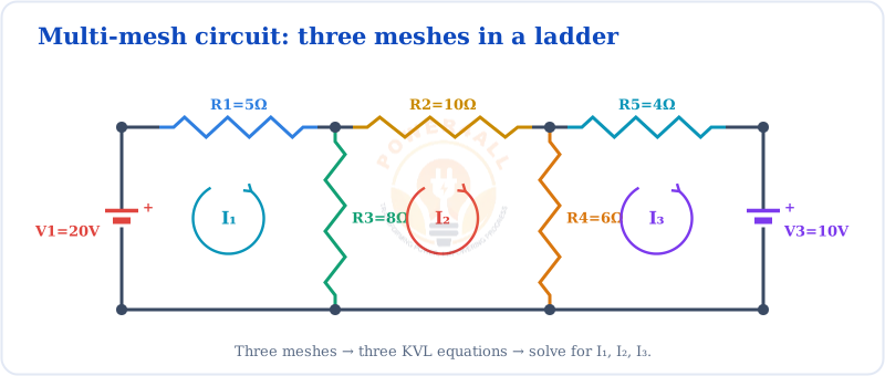
Given: V₁ = 20V, V₃ = 10V, R₁ = 5Ω, R₂ = 10Ω, R₃ = 8Ω, R₄ = 6Ω, R₅ = 4Ω
Find: Mesh currents I₁, I₂, and I₃
Complete Solution for Example 2
This example demonstrates mesh analysis with three loops and multiple voltage sources.
KVL Equations Development
| Mesh | KVL Equation | Simplified Form |
|---|---|---|
| Mesh 1 | 20 - 5I₁ - 8(I₁ - I₂) = 0 | 13I₁ - 8I₂ = 20 |
| Mesh 2 | 8(I₂ - I₁) - 10I₂ - 6(I₂ - I₃) = 0 | -8I₁ + 24I₂ - 6I₃ = 0 |
| Mesh 3 | 6(I₃ - I₂) - 4I₃ - 10 = 0 | -6I₂ + 10I₃ = 10 |
Matrix Solution
[13 -8 0 ][I₁] [20]
[-8 24 -6 ][I₂] = [0 ]
[0 -6 10 ][I₃] [10]
Matrix equation for three-mesh system
- Calculate determinant: Δ = 1840
- Use Cramer's rule or matrix inversion
- Solve systematically for each current
- I₁ = 1.89A (clockwise in mesh 1)
- I₂ = 0.43A (clockwise in mesh 2)
- I₃ = 1.26A (clockwise in mesh 3)
Verification
Always verify results using KCL at nodes and power balance. All currents are positive, indicating they flow in the assumed clockwise directions.
Example 3: Circuit with Dependent Source (Source: Testbook)
Problem Statement
Circuit with Dependent Voltage Source
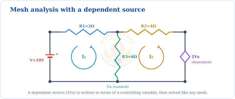
Given: V = 10V, dependent voltage source = 2Vₓ (where Vₓ is voltage across R₃), R₁ = 2Ω, R₂ = 4Ω, R₃ = 6Ω
Find: All mesh currents and the controlling voltage Vₓ
Complete Solution for Example 3
Dependent sources require additional constraint equations relating the controlling variable to mesh currents.
- Vₓ is the voltage across the 6Ω resistor (R₃)
- Current through 6Ω resistor = I₁ - I₂
- Therefore: Vₓ = 6(I₁ - I₂)
- Mesh 1: 10 - 2I₁ - 6(I₁ - I₂) = 0
- Mesh 2: 6(I₂ - I₁) - 4I₂ - 2Vₓ = 0
- Substitute Vₓ = 6(I₁ - I₂) into mesh 2 equation
- Equation 1: 10 - 8I₁ + 6I₂ = 0 → 8I₁ - 6I₂ = 10
- Equation 2: 6I₂ - I₁ - 4I₂ - 12(I₁ - I₂) = 0
- Simplified: -13I₁ + 14I₂ = 0 → I₂ = (13/14)I₁
- Substituting: 8I₁ - 6(13/14)I₁ = 10
- Therefore: I₁ = 2.8A, I₂ = 2.6A, Vₓ = 6(2.8-2.6) = 1.2V
Key Learning
Dependent sources create coupling between meshes that wouldn't normally be connected. Always verify that your dependent source constraint equation is correct and properly substituted.
Supermesh Analysis: Handling Current Sources
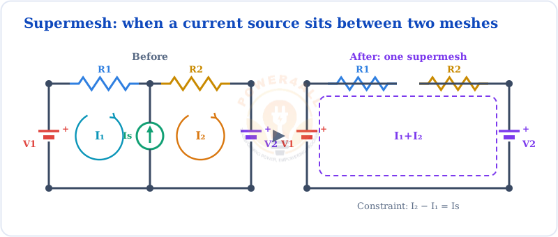
When a current source appears between two meshes, traditional mesh analysis becomes problematic because we cannot directly apply KVL around loops containing current sources. Supermesh analysis provides a systematic solution by combining meshes that share a current source.
Reference: Supermesh concept from GeeksforGeeks - Mesh Analysis
Supermesh Formation
When to Use Supermesh Analysis
Current Source Issues
Why regular mesh analysis fails
Problems with Current Sources
- Voltage unknown: Current sources don't have a fixed voltage drop
- KVL disrupted: Cannot write KVL equation around loop with current source
- Variable count mismatch: Fewer equations than unknown currents
- Circuit analysis stuck: Traditional approach cannot proceed
Typical Scenario
Two meshes connected by 3A current source:
- Mesh 1: Cannot complete KVL due to current source
- Mesh 2: Same problem from other side
- Need alternative approach: supermesh
Supermesh Solution
How supermesh solves the problem
Supermesh Approach
- Combine meshes: Treat two meshes as one larger loop
- Exclude current source: Write KVL around combined path
- Add constraint: Use current source value as additional equation
- Solve system: Now have enough equations for solution
I₂ - I₁ = I_source
Current constraint from current source
Step-by-Step Supermesh Procedure
Detailed Supermesh Example
Complete Worked Example with Step-by-Step Solution
Supermesh Example Circuit
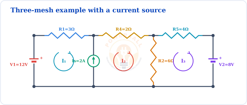
Given: V₁ = 12V, V₂ = 8V, Is = 2A, R₁ = 3Ω, R₂ = 6Ω, R₄ = 2Ω, R₅ = 4Ω
Find: All mesh currents I₁, I₂, and I₃
Solution Process
- 2A current source is shared between mesh 1 and mesh 2
- Mesh 3 is independent (no shared current source)
- Need to form supermesh from meshes 1 and 2
- Supermesh path: Start at top-left, go through R₁, R₄, R₂, back to start
- Exclude the current source branch in KVL
- KVL equation: 12 - 3I₁ - 2(I₁ - I₃) - 6I₂ = 0
- Simplified: 12 - 5I₁ + 2I₃ - 6I₂ = 0
- Current source forces: I₂ - I₁ = 2A
- This gives us: I₂ = I₁ + 2
- KVL around mesh 3: 2(I₃ - I₁) - 4I₃ + 8 = 0
- Simplified: 2I₃ - 2I₁ - 4I₃ + 8 = 0
- Final form: -2I₁ - 2I₃ + 8 = 0
- Equation 1: 5I₁ + 6I₂ - 2I₃ = 12
- Equation 2: I₂ - I₁ = 2
- Equation 3: 2I₁ + 2I₃ = 8
- From equation 3: I₃ = 4 - I₁
- Substitute and solve: I₁ = 1A, I₂ = 3A, I₃ = 3A
| Mesh Current | Calculated Value | Direction | Physical Meaning |
|---|---|---|---|
| I₁ | 1A | Clockwise | Current circulates clockwise in mesh 1 |
| I₂ | 3A | Clockwise | Current circulates clockwise in mesh 2 |
| I₃ | 3A | Clockwise | Current circulates clockwise in mesh 3 |
Verification
Check current source constraint: I₂ - I₁ = 3A - 1A = 2A ✓
Check power balance: Power supplied = Power dissipated ✓
Frequently Asked Questions
What is the main difference between mesh and nodal analysis?
Mesh analysis uses KVL and focuses on loop currents, while nodal analysis uses KCL and focuses on node voltages. Mesh analysis works only with planar circuits but handles voltage sources easily, while nodal analysis works with any circuit topology but requires special treatment for voltage sources.
When should I use supermesh analysis?
Use supermesh analysis when there's a current source shared between two meshes. You cannot apply KVL directly around a loop containing a current source, so you combine the affected meshes into a supermesh and add a constraint equation for the current source.
How do I know if a circuit is planar?
A circuit is planar if it can be redrawn on a flat surface without any wires crossing. Try redrawing the circuit in different configurations. If you can eliminate all crossings, it's planar. Common non-planar circuits include the complete graph K₅ and utility graphs like K₃,₃.
Conclusion
Mesh analysis is a fundamental and powerful technique for solving electrical circuits. Throughout this comprehensive guide, we've explored everything from basic principles to advanced applications, providing you with the knowledge and tools needed to tackle complex circuit analysis problems with confidence.
What You've Learned
- Fundamental principles of mesh analysis and KVL application
- Step-by-step procedures for systematic circuit analysis
- Advanced techniques including supermesh and matrix methods
- Practical applications in real-world engineering scenarios
- Comparison with other methods to choose the best approach
Remember that mastery comes through practice. Start with simple two-mesh circuits and gradually work your way up to more complex networks. Always verify your results and don't hesitate to use alternative methods when mesh analysis becomes unwieldy.
References for Examples and Images: