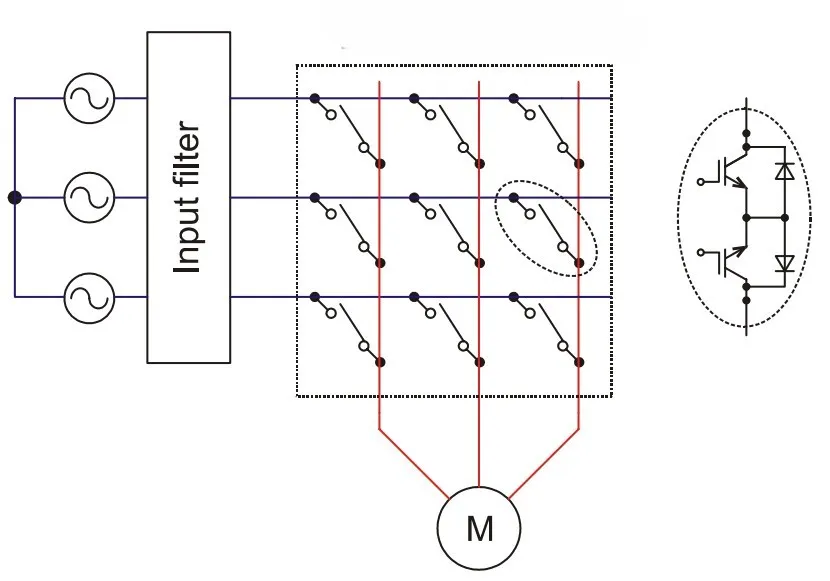
What is a direct matrix converter?
A direct matrix converter (DMC) is a direct AC-to-AC power converter. It links a three-phase input to a three-phase output through a 3×3 array of nine bidirectional switches — one switch at every crossing of an input phase and an output phase. There is no DC-link capacitor or inductor: energy flows straight from input to output, and each output phase is built moment-to-moment from pieces of the three input voltages.
How the output is synthesised
Using space-vector (or Venturini) modulation, the nine switches are operated so that the short-term average of each output phase follows a reference sine vref(t) = q·Vim·sin(ωot). It is convenient to picture a fictitious DC link equal to the instantaneous difference between the largest and smallest input phase voltages; the output is then a PWM of this envelope, exactly as in the indirect matrix converter.
Output voltage and the 0.866 limit
Because the output is assembled only from the available input voltages, the largest undistorted output phase voltage is 0.866·Vim. Demanding more (q > 0.866) pushes the converter into over-modulation, where the output gains low-order harmonics. This simulator builds the real switched waveform and extracts its fundamental by FFT, confirming Vo = q·Vim to numerical precision in the linear range.
Why no DC link? — topic-specific
Removing the DC-link electrolytic capacitor is the whole point of a matrix converter. The benefits are a compact, long-life converter, sinusoidal input currents with adjustable (near-unity) input power factor, and inherent four-quadrant operation (regeneration back to the grid). The costs are the 0.866 voltage ceiling, nine bidirectional switches (18 IGBTs) needing careful four-step commutation, and sensitivity to input-voltage disturbances.
Applications
Compact motor drives where DC-link capacitors are undesirable — aerospace and defence actuators, wind-turbine and marine drives, and integrated motor-converter modules. Compare the two equivalent realisations: the indirect matrix converter and the reduced-switch sparse matrix converter.
Frequently asked questions
What is a direct matrix converter?
A direct AC-to-AC converter that connects a three-phase input to a three-phase output through a 3×3 array of nine bidirectional switches, with no DC-link capacitor. Each output phase is built from pieces of the input voltages by fast switching.
What is the maximum voltage transfer ratio?
Vo = q·Vim with a linear-range maximum of q = √3/2 ≈ 0.866. Beyond that the converter over-modulates and the output distorts.
Why is there no DC link?
The nine bidirectional switches pass energy directly from input to output, so no capacitor is needed. This gives sinusoidal input currents, near-unity input power factor and four-quadrant operation.
How many switches and IGBTs does it use?
Nine bidirectional switches — usually built as 18 IGBTs (two per switch) with anti-parallel diodes — plus four-step commutation logic.