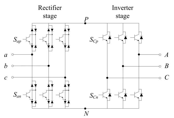
What is a sparse matrix converter?
A sparse matrix converter (SMC) is a reduced-switch version of the indirect matrix converter. It keeps the same two-stage structure — a rectifier that forms an imaginary DC link (no capacitor) and a six-switch inverter — but uses fewer active devices. The version shown here is built from 12 IGBTs and 30 diodes, compared with 18 IGBTs in the direct/indirect converters.
Same performance, fewer switches
Because the rectifier stage only needs to carry unidirectional DC-link current, several bidirectional switches can be replaced by a single IGBT inside a diode bridge. The result matches the indirect converter's waveforms and its q ≤ 0.866 voltage ceiling while cutting cost, gate-drive count and control complexity. Variants include the very sparse (VSMC) and ultra-sparse matrix converters.
Output voltage and the 0.866 limit
The inverter uses space-vector modulation referenced to the imaginary DC link, so each output phase tracks q·Vim·sin(ωot). This simulator confirms Vo = q·Vim by FFT of the real switched waveform.
Zero-current commutation & control — topic-specific
Like the indirect converter, the SMC commutates while the DC-link current is zero, which simplifies protection. Its low device count also makes it a favourite test-bed for advanced control such as model-predictive current control. It keeps the matrix-converter advantages: no DC-link capacitor, sinusoidal input currents and near-unity input power factor.
Applications
Cost-sensitive capacitor-free drives and research platforms for predictive control. Compare the direct matrix converter and the indirect matrix converter.
Frequently asked questions
What is a sparse matrix converter?
A reduced-switch version of the indirect matrix converter. It forms an imaginary DC link with no capacitor and drives a six-switch inverter, using fewer active devices (here 12 IGBTs and 30 diodes) than the 18-IGBT direct/indirect converters.
What is the maximum voltage transfer ratio?
Vo = q·Vim with a linear-range maximum of q = √3/2 ≈ 0.866, the same as the direct and indirect matrix converters.
How is it different from the indirect matrix converter?
It has the same two-stage behaviour but fewer switches, because the rectifier carries only unidirectional DC-link current. This lowers cost and control complexity while keeping the same performance and 0.866 voltage ceiling.
What are very sparse and ultra-sparse matrix converters?
Further reduced-switch variants of the sparse matrix converter that trade a little flexibility for even fewer devices, used where cost and size matter most.