Single-Phase Semi-Converter
A single-phase semi-converter is a half-controlled bridge rectifier — two SCRs and two diodes — that gives smooth, phase-controlled DC output for one-quadrant operation.
- Introduction
- What is a Single-Phase Semi-Converter?
- Types of Single-Phase Semi-Converter
- Circuit Diagram & Construction
- Modes of Operation (R Load)
- Input & Output Waveforms (Voltage & Current)
- Key Parameters & Formulas
- Effect of the Firing Angle α
- Semi-Converter vs Full-Converter
- Advantages & Disadvantages
- Applications
- Frequently Asked Questions – FAQs
- Related Topics
Introduction
A controlled rectifier converts fixed AC into adjustable DC by delaying when its thyristors (SCRs) are switched on. In the fully-controlled bridge, all four devices are SCRs, so the output can swing negative and the converter can even return power to the source (inversion). The single-phase semi-converter takes a simpler, cheaper route: it replaces two of those SCRs with ordinary diodes, forming a half-controlled bridge.
This one change means the output voltage can be smoothly controlled from maximum down to zero — but it can never go negative. The semi-converter therefore works in a single quadrant (positive voltage, positive current) as a pure controlled rectifier, and as a bonus it draws a better input power factor than the full converter at the same firing angle. In this tutorial we cover its circuit, the step-by-step modes of operation with a resistive load, the full set of voltage and current waveforms, and all the key formulas.
What is a Single-Phase Semi-Converter?
A single-phase semi-converter (also called a half-controlled bridge rectifier) is a single-phase AC-to-DC converter built from a mix of controlled and uncontrolled devices: two thyristors (T1, T2) provide the phase control, while two diodes (D1, D2) provide an uncontrolled return path. A freewheeling diode Dm is usually connected across the load to carry the inductive load current when the supply is not delivering power.
By delaying the SCR turn-on by a firing (delay) angle α, the average DC output is varied. The average output voltage of a single-phase semi-converter is:
Because the diodes and the freewheeling path prevent the output from ever reversing polarity, the semi-converter is a one-quadrant converter: it can only rectify (deliver power from AC to DC), and cannot feed energy back from the DC load to the AC source.
Types of Single-Phase Semi-Converter
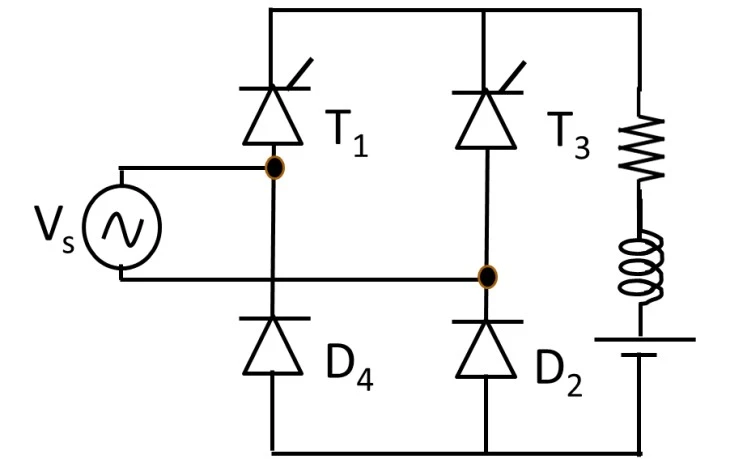
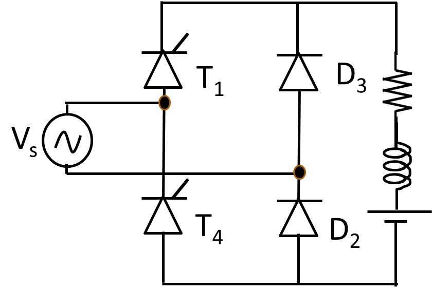
Depending on how the two thyristors and two diodes are arranged in the bridge, a single-phase semi-converter is built in one of two configurations. Both use 2 SCRs + 2 diodes, both are half-controlled and one-quadrant, and both give the same average output voltage Vo = (Vm/π)(1 + cosα) — they differ mainly in device arrangement and gate-drive requirements.
1. Symmetrical Semi-Converter
In the symmetrical configuration the two thyristors (T1, T2) occupy the two upper arms and share a common cathode connected to the positive DC terminal, while the two diodes (D1, D2) occupy the two lower arms with a common anode at the negative terminal. Because both SCR cathodes sit at the same point, their gate-drive (triggering) circuits can share a common reference, which makes control simpler. In the positive half-cycle T1 and D1 conduct; in the negative half-cycle T2 and D2 conduct. This is the configuration analysed on this page.
2. Asymmetrical Semi-Converter
In the asymmetrical configuration each leg of the bridge contains one thyristor and one diode. The two thyristors therefore do not share a common cathode, so each SCR generally needs its own isolated gate-drive circuit. The freewheeling action during the zero-output interval is provided mainly by the two diodes. Electrically it delivers the same controlled DC output as the symmetrical converter; the choice between the two is driven by triggering, isolation and layout considerations.
Circuit Diagram & Construction
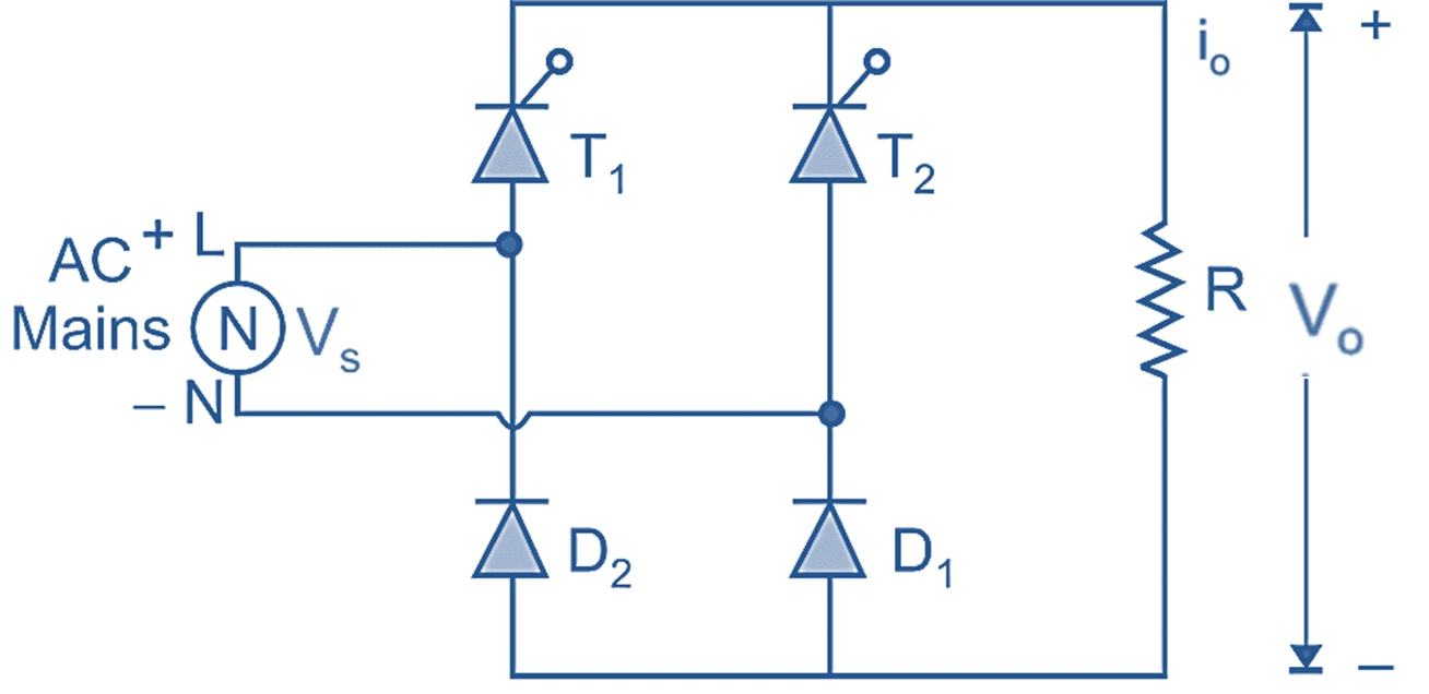
A single-phase semi-converter (symmetrical configuration) is built from four bridge devices plus a freewheeling diode:
- Two thyristors (SCRs) — T1 and T2 — form the controlled (upper) half of the bridge.
- Two diodes — D1 and D2 — form the uncontrolled (lower) half of the bridge.
- One freewheeling diode — Dm — connected directly across the load.
- A load that is usually inductive (R–L), such as a DC motor armature or a filtered DC supply.
The AC supply feeds the bridge; T1 pairs with D1 to handle the positive half-cycle, and T2 pairs with D2 to handle the negative half-cycle. Whichever pair conducts, the load current is steered in the same direction, giving a DC output. For a purely resistive load the diodes alone provide the return path; for an inductive (R–L) load the freewheeling diode Dm clamps the output to zero (and keeps the current flowing) whenever the supply voltage tries to go negative.
Modes of Operation (R Load)
Consider the symmetrical semi-converter feeding a resistive (R) load, with the two thyristors fired at a delay angle α. Over one full input cycle (0 to 2π) the circuit passes through three distinct modes. In each conducting mode a thyristor and a diode form a series path for the load current; between them there is a dead interval in which the output is zero.
Mode 1 — T1 & D1 conduct (α ≤ ωt < π)
During the positive half-cycle thyristor T1 is forward-biased. When T1 is fired at ωt = α, it turns on and conducts together with diode D1, connecting the load directly across the supply. Current flows source → T1 → load → D1 → source, so the output equals the supply voltage, vo = vs = Vm sinωt, and the load current is io = vo/R. Before firing (0 to α) no device conducts, so the output stays at zero — this is how the delay angle controls the average voltage.
Mode 2 — No device conducts, vo = 0 (π ≤ ωt < π+α)
At ωt = π the supply voltage falls to zero, so T1 (with D1) turns off by natural commutation. In the interval from π to π+α the next thyristor T2 has not yet been fired, and with a resistive load there is no stored energy to keep current flowing. Hence no device conducts, the load current is zero, and the output voltage is held at vo = 0 V.
Mode 3 — T2 & D2 conduct (π+α ≤ ωt < 2π)
In the negative half-cycle thyristor T2 is forward-biased. When T2 is fired at ωt = π+α, it conducts with diode D2, again connecting the load to the supply — now current flows source → T2 → load → D2 → source. The bridge steers this current through the load in the same direction as before, so the output is the rectified magnitude vo = |Vm sinωt|. At ωt = 2π the supply returns to zero, T2 and D2 turn off, and the whole cycle repeats.
Input & Output Waveforms (Voltage & Current)
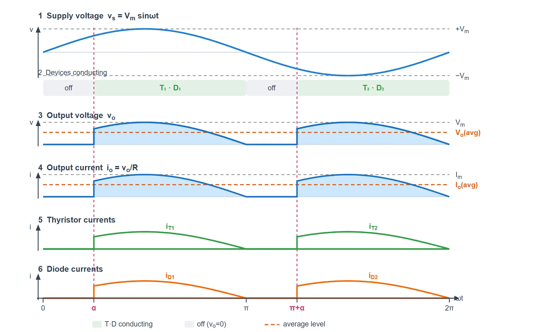
Every trace below is computed directly from the modes above (drawn for a firing angle α = 45°, symmetrical semi-converter with an R load). The six panels share one time axis (ωt): the AC supply voltage, the conducting devices, the output voltage, the output current, and the individual thyristor and diode currents.
Reading the Waveform
- Supply voltage vs: the ordinary AC sine, Vm sinωt, over one full cycle (0 to 2π). The pink dashed lines mark the firing instants α and π+α.
- Devices conducting: T1·D1 power the load from α to π (Mode 1); both pairs are off from π to π+α (Mode 2, vo = 0); then T2·D2 power the load from π+α to 2π (Mode 3).
- Output voltage vo: a chopped sine hump from α to π, zero from π to π+α, and another hump from π+α to 2π. It never goes negative — one-quadrant operation. The orange dashed line is the average, Vo = (Vm/π)(1 + cosα).
- Output current io: for a resistive load io = vo/R, so it has exactly the same chopped-sine shape as vo, scaled by 1/R. Its average is Io = Vo/R.
- Thyristor currents iT1, iT2: each SCR carries the load current only while it conducts — iT1 is a hump from α to π, and iT2 is a hump from π+α to 2π. Each SCR conducts once per cycle.
- Diode currents iD1, iD2: because a diode is in series with its thyristor, iD1 = iT1 (α to π) and iD2 = iT2 (π+α to 2π). The diode carries the same current, at the same time, as its partner SCR.
- R vs R–L load: with an inductive load plus freewheeling diode Dm, the voltage waveform is unchanged, but the currents (io, and the device currents) become flat-topped blocks instead of humps, because the inductor smooths the current to a nearly constant value.
Key Parameters & Formulas
For an ideal single-phase semi-converter feeding its load, with Vm the peak supply voltage and α the firing angle:
| Quantity | Formula & Value |
|---|---|
| Average (DC) output voltage | Vo = (Vm/π)(1 + cosα) |
| Maximum output (at α = 0°) | Vo = 2Vm/π ≈ 0.637 Vm |
| Minimum output (at α = 180°) | Vo = 0 |
| RMS output voltage | Vrms = (Vm/√2)√[(1/π)(π − α + ½sin2α)] |
| Average load current | Io = Vo/R = (Vm/πR)(1 + cosα) |
| Output ripple frequency | fripple = 2f (100 Hz for a 50 Hz supply) |
| Quadrant of operation | One quadrant (+V, +I — rectifying only) |
| Peak Inverse Voltage (each device) | PIV = Vm |
The average voltage varies smoothly from 2Vm/π (full output, α = 0°) down to 0 (α = 180°), which is exactly how the semi-converter controls DC power to the load.
Effect of the Firing Angle α
The firing angle α is the single control knob of the converter. Delaying it reduces the conducting portion of each half-cycle, so both the average and RMS output fall. A few representative points from Vo = (Vm/π)(1 + cosα):
| Firing angle α | Average output Vo |
|---|---|
| 0° | 2Vm/π ≈ 0.637 Vm (maximum) |
| 60° | ≈ 0.477 Vm |
| 90° | Vm/π ≈ 0.318 Vm |
| 120° | ≈ 0.159 Vm |
| 180° | 0 (minimum) |
Unlike the full converter, the semi-converter's output cannot become negative no matter how large α is — so it cannot operate in the inversion mode and cannot feed energy back to the AC supply.
Semi-Converter vs Full-Converter
Both are single-phase phase-controlled bridges, but they make very different trade-offs:
| Parameter | Semi-Converter (half-controlled) | Full-Converter (fully-controlled) |
|---|---|---|
| Devices | 2 SCRs + 2 diodes | 4 SCRs |
| Average output | Vo = (Vm/π)(1 + cosα) | Vo = (2Vm/π)cosα |
| Output polarity | Always positive (0 → +) | Positive or negative |
| Quadrants | One quadrant (rectifier only) | Two quadrants (rectifier + inverter) |
| Energy feedback to source | Not possible | Possible (inversion mode) |
| Freewheeling action | Inherent (or diode Dm) | None (needs external diode) |
| Input power factor | Better (for the same α) | Lower |
| Cost & control | Lower cost, simpler firing | Higher cost, more complex |
Advantages & Disadvantages
Advantages
- Lower cost: two diodes replace two SCRs, so fewer gate-drive and control circuits are needed.
- Better input power factor than a full converter at the same firing angle, thanks to the freewheeling action.
- Simpler control: only two thyristors need firing pulses.
- Smooth DC control from maximum down to zero by adjusting α.
- The freewheeling diode reduces load-current ripple and protects the SCRs from large reverse transients.
Disadvantages
- One-quadrant only: output cannot go negative, so it cannot invert or return energy to the source.
- Not suitable for applications needing regenerative braking or reversible DC drives.
- Output contains ripple and harmonics that may need filtering for sensitive loads.
- Input current is non-sinusoidal, introducing harmonics into the AC supply.
Applications
- DC motor speed control where one-directional (motoring-only) operation is enough — fans, pumps, conveyors.
- Battery charging and regulated DC power supplies with adjustable output.
- Electroplating, anodizing and electrolysis that need controllable DC current.
- Traction and industrial drives supplying large DC motors from a single-phase AC line where reverse power flow is not required.
- Heater and lighting power control for resistive DC loads.