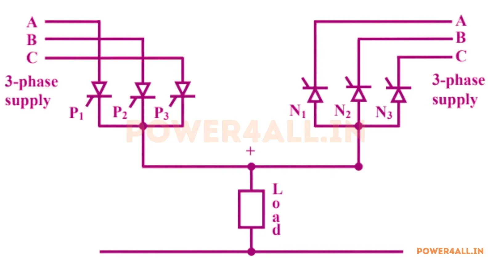
What is a three-phase to single-phase half-wave cycloconverter?
A cycloconverter is a direct AC-to-AC frequency changer: it converts a fixed-frequency AC supply into a variable, lower-frequency AC output without any intermediate DC link. The three-phase to single-phase half-wave version uses two 3-pulse phase-controlled converter groups connected in anti-parallel across one single-phase load — a positive group (P) that carries positive load current and a negative group (N) that carries negative load current.
Cosine-wave firing modulation
The trick is to modulate the firing angle α continuously instead of holding it fixed. Each group is fired so that cos α(t) = r·sin(ωot), where ωo = 2π·fo is the desired output angular frequency and r is the modulation ratio. Because the mean output of a phase-controlled converter is Vd0·cos α, this makes the local average of the output follow Vd0·r·sin(ωot) — a clean low-frequency sine.
Fundamental output voltage
The peak of the fundamental output equals the modulation ratio times the maximum mean converter output:
where Vm is the peak phase voltage and Vd0 is the 3-pulse converter's maximum mean output (the same value that appears in a three-phase half-wave controlled rectifier). This simulator builds the output by the actual cosine-crossing firing scheme and extracts the fundamental by FFT, so the measured Vo1 matches r·Vd0 to numerical precision in the recommended frequency range.
Output frequency limit & waveform quality — topic-specific
The output is assembled from segments of the input phases, so the number of segments per output cycle is p·fi/fo (here p = 3). The higher the ratio fo/fi, the fewer segments per output cycle, the larger the harmonic distortion, and the more the fundamental falls below r·Vd0. For this reason a 3-pulse cycloconverter is normally limited to fo ≤ fi/3; a 6-pulse (bridge) version can reach roughly fi/2 with lower distortion.
Applications
Cycloconverters drive large, low-speed machines directly — ball mills, cement kilns, mine hoists and rolling mills — and supply constant-frequency aircraft power. See also the three-phase to single-phase full-bridge cycloconverter, the three-phase to three-phase versions and the single-phase to single-phase cycloconverter.
Frequently asked questions
What is a three-phase to single-phase half-wave cycloconverter?
A direct AC-to-AC frequency changer that turns a three-phase supply into a lower-frequency single-phase output using two 3-pulse converter groups (positive and negative) with cosine-modulated firing — no DC link.
What is the fundamental output voltage?
Vo1(peak) = r·Vd0 with Vd0 = (3√3/2π)·Vm ≈ 0.827·Vm, so Vo1(rms) = r·Vd0/√2. r is the modulation ratio (0–1).
Why keep fo below fi/3?
The output is made of input-waveform segments; there are p·fi/fo segments per output cycle. As fo/fi rises the count drops, distortion rises and the fundamental droops. fo ≤ fi/3 keeps a 3-pulse output clean.
What are cycloconverters used for?
Large low-speed drives (mills, kilns, hoists) and constant-frequency aircraft supplies — smooth low-frequency output with four-quadrant operation and no DC link.