Three-Phase AC Voltage Controller
Six thyristors — one anti-parallel pair per phase — vary the RMS voltage supplied to a three-phase load while the supply frequency stays fixed.
Introduction
A three-phase AC voltage controller is a power-electronic circuit that takes a fixed three-phase AC supply and delivers an adjustable three-phase AC voltage of the same frequency to the load. Like its single-phase cousin, it is a direct AC-to-AC converter — there is no intermediate DC stage, and it changes only the RMS magnitude of the voltage, never the frequency.
It is the natural choice for controlling larger three-phase loads — induction-motor soft-starters, industrial heating elements, and lighting banks — where a single-phase controller would be too small or would unbalance the supply. The control is done with six thyristors: one back-to-back (anti-parallel) pair in each of the three lines, triggered in a fixed sequence to chop each phase's sine wave by a chosen firing angle (α).
This page looks at the most common arrangement: the three-phase, three-wire controller feeding a balanced star-connected resistive load. If you are new to the idea, it helps to first read the single-phase AC voltage controller, because each phase here behaves much like that simpler circuit.
Block Diagram
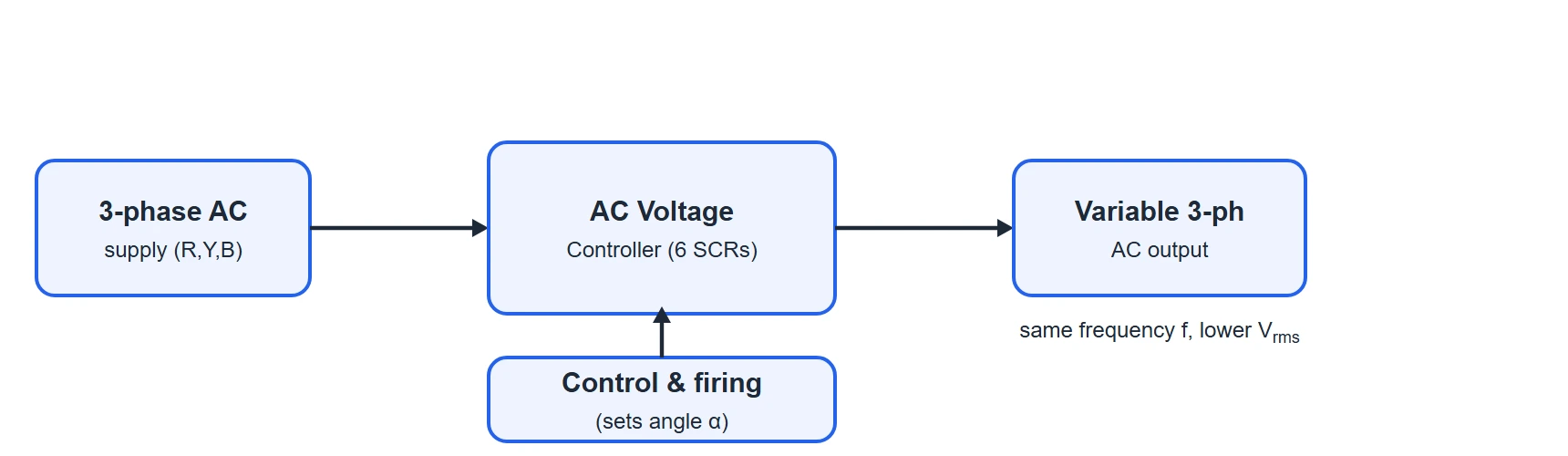
At the block level the controller sits between the three-phase supply and the load. A single control & firing unit generates six gate pulses — one for each thyristor — correctly phased so that every device is triggered at the same firing angle relative to its own phase.
Circuit Diagram & Construction
The power circuit of the three-phase, three-wire AC voltage controller is shown below. It is built from three identical single-phase controllers — one in each supply line — sharing a common three-phase source and a common star-connected load.
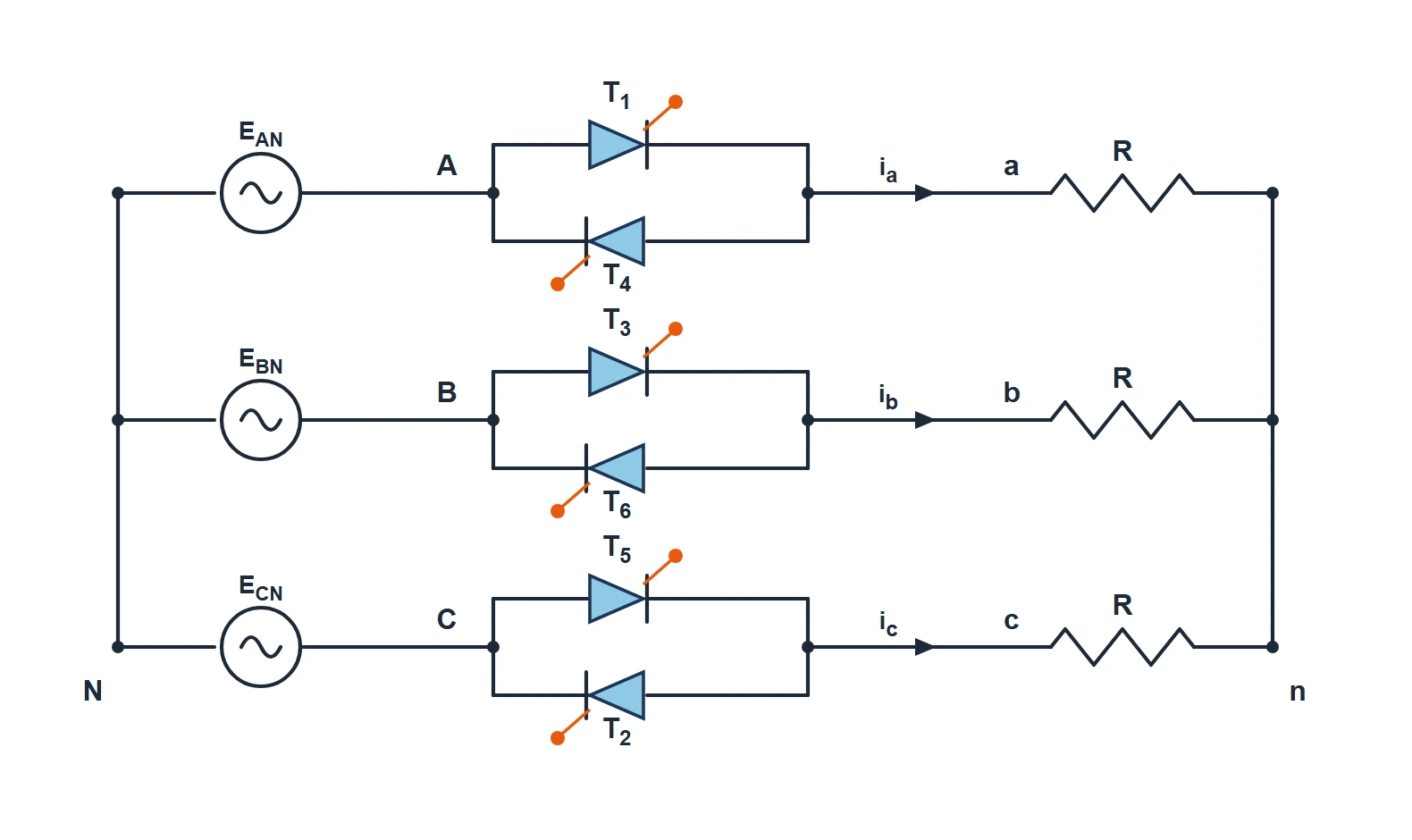
Reading the circuit from left to right:
- The source is a balanced three-phase supply drawn in star: three phase voltages EAN, EBN, ECN measured from the common supply neutral N. The three lines are labelled A, B and C.
- Each line passes through an anti-parallel (back-to-back) thyristor pair, exactly like the single-phase controller. There are therefore six thyristors in total: T1 & T4 in line A, T3 & T6 in line B, and T5 & T2 in line C. In each pair, one thyristor carries the positive half-cycle current and the other the negative half-cycle current.
- The three controlled line currents ia, ib, ic feed the balanced star-connected load — three equal resistors R joined at the load neutral n.
- Crucially, this is a three-wire connection: the load neutral n is NOT joined to the supply neutral N. The neutral is isolated.
The odd numbering (T1, T3, T5 for the "upper" devices and T4, T6, T2 for the "lower" devices) is not random — it is the order in which the thyristors are fired, which we look at next.
Firing Sequence
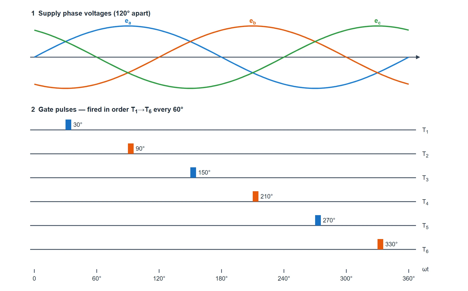
The six thyristors are triggered one after another in ascending order — T1, T2, T3, T4, T5, T6 — and the gap between successive firings is exactly 60° (one-sixth of a cycle). After T6 the sequence returns to T1, so there are six firing pulses in every complete cycle.
Each thyristor is fired at the same delay angle α measured from the point where its own phase voltage would naturally let it start conducting. Because the three phases are 120° apart and each phase has two devices (180° apart), triggering the six devices at a steady 60° spacing keeps the load perfectly balanced.
Modes of Operation
How many thyristors conduct at once depends entirely on the firing angle α. Remember the golden rule from above: at least two lines must conduct together to give the current somewhere to go. As α increases, the circuit passes through three clearly different modes. (These are described in words only — the circuit itself is the one shown in Figure 2.)
Mode I — Firing angle 0° to 60°
For small firing angles the circuit alternates, moment by moment, between three thyristors conducting and two thyristors conducting.
- When all three lines conduct, the load is connected just like a normal three-phase star, so each resistor receives its full phase voltage.
- When only two lines conduct, those two load resistors are effectively in series across one line-to-line voltage, so each of them receives half the line voltage.
The fraction of time spent with three devices on shrinks steadily as α grows — it is 100% at α = 0° and falls linearly to 0% at α = 60°, where the three-conduction intervals disappear entirely.
Mode II — Firing angle 60° to 90°
In this range exactly two thyristors conduct at every instant — never three, and never fewer. The current continuously hands over from one pair of lines to the next as the sequence advances, so the load always sees a piece of a line-to-line voltage. There are no gaps and no full-phase intervals; this is the "cleanest" of the three modes to analyse.
Mode III — Firing angle 90° to 150°
Beyond 90° the firing is so late that, for part of every 60° window, no valid pair of thyristors is simultaneously able to conduct. During those intervals the load is completely disconnected and its voltage is zero. So the output now alternates between two thyristors conducting and no thyristor conducting. The dead intervals grow as α increases, and at α = 150° they fill the whole cycle — the output falls to zero.
Waveforms & Explanation
First, the input side and the gating. The three supply phase voltages are 120° apart, and the six gate pulses are spaced 60° apart in the order T1→T6, each delayed by the firing angle α (shown here for α = 30°).
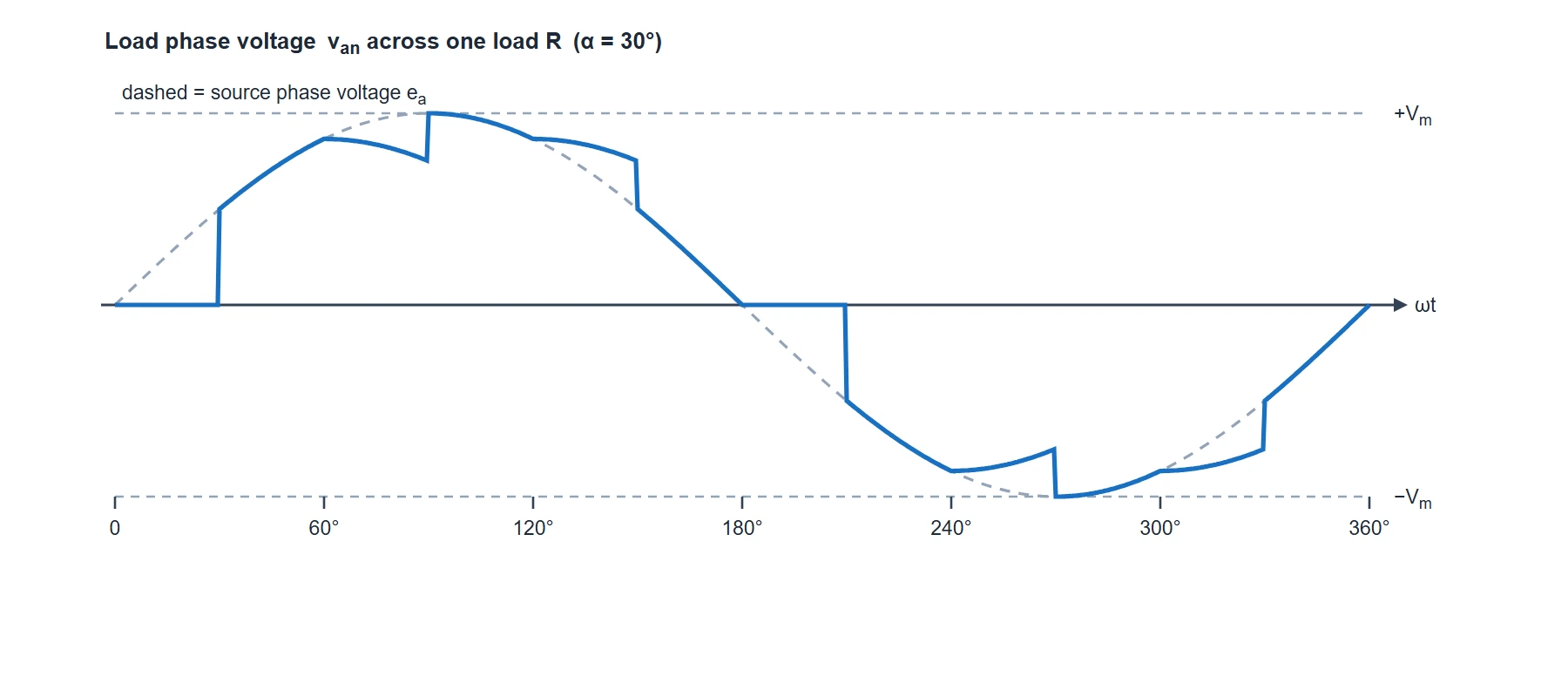
Now the output. The waveform below is the voltage across one resistor of the star load (van) for α = 30°, which lies in Mode I. It is a composite waveform, stitched together from two kinds of arc, and it is plotted against the source phase voltage (dashed) for reference.
Reading the Load Waveform
- It follows the dashed phase voltage where three devices conduct. In those intervals the load is a normal three-phase star, so van sits exactly on the source phase voltage ea (peak Vm).
- It drops onto a smaller arc where only two devices conduct. Here the resistor gets half of a line-to-line voltage, so the trace steps down to a lower level between the full-phase intervals.
- Sharp steps mark the switching instants. Every time a thyristor is fired or a device stops conducting, the number of conducting lines changes, and the load voltage jumps from one arc to the other — these are the switching edges that create harmonics.
- The waveform is symmetrical. The negative half is a mirror image of the positive half, so the average over a full cycle is zero — there is no DC component, exactly as an AC output should be.
- Higher α = smaller waveform. As the firing angle grows, the full-phase arcs shrink (Mode I), then vanish (Mode II), and finally flat zero gaps appear (Mode III) — steadily lowering the RMS value.
Output Voltage & Formulas
Because the load voltage is made of different arcs in each mode, the RMS output is worked out mode by mode. Taking Vph as the RMS value of the supply phase voltage and α in radians, the widely-used result for Mode I (0° ≤ α ≤ 60°) is:
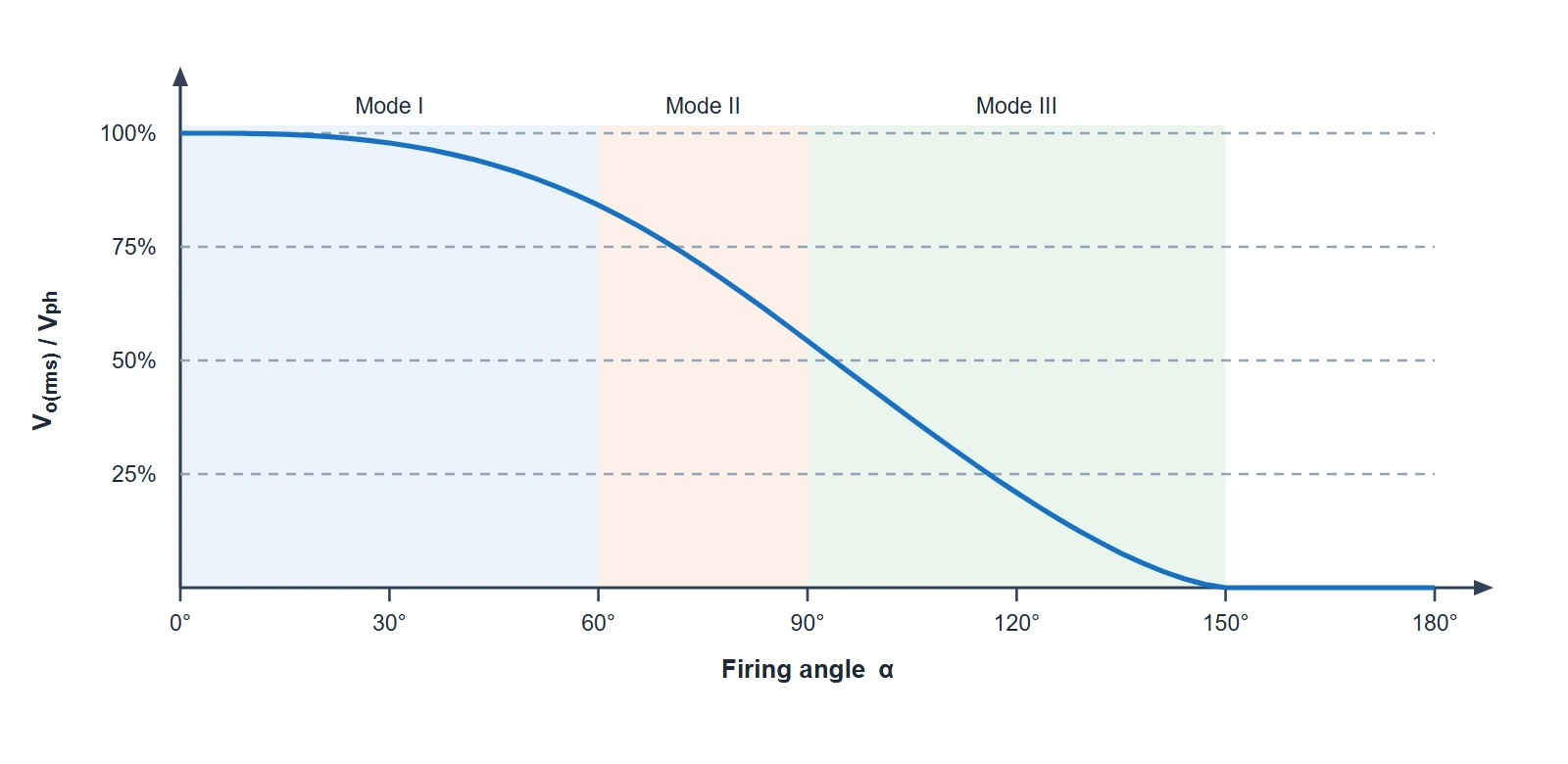
Modes II and III have their own longer expressions, but the important behaviour is easiest to see as a table of the RMS output (as a percentage of the full phase voltage) against firing angle:
| Firing angle α | Vo(rms) / Vph |
|---|---|
| 0° | 100% (full output) |
| 30° | 97.8% |
| 60° (end of Mode I) | 84.1% |
| 90° (end of Mode II) | 54.2% |
| 120° | 20.8% |
| 150° (maximum) | 0% (output off) |
These values come from evaluating the load-voltage waveform of Figure 4 for each firing angle. Two useful facts fall straight out of them:
- The useful control range is α = 0° to 150° — beyond 150° the output is already zero.
- The average output voltage over a full cycle is zero (the waveform is symmetrical), so the load current has no DC component.
Control Characteristic
Plotting the RMS output against firing angle gives the control characteristic. The three operating modes are shaded, and you can see the curve change slope as it crosses from one mode into the next before reaching zero at 150°.
Advantages & Disadvantages
Advantages
- Smooth, continuous control of a balanced three-phase output from full voltage down to zero.
- Full-wave, symmetrical operation — no DC component in the line currents.
- Simple, rugged and efficient: no moving parts, natural (line) commutation, no forced turn-off circuitry.
- Suited to high-power loads that a single-phase controller cannot handle.
Disadvantages
- The chopped output is rich in harmonics, especially at large firing angles, which may need filtering.
- Poor input power factor as the firing angle increases.
- Needs six thyristors with six isolated gate drives fired in a precise 60° sequence — more complex control than a single-phase circuit.
- Only reduces voltage at a fixed frequency — it cannot boost the voltage or change the frequency.
Applications
- Induction-motor soft-starters — ramping the stator voltage to limit starting current and torque.
- Industrial heating — furnaces, ovens and large resistive heater banks.
- Three-phase lighting control for stadiums and large halls.
- Speed control of three-phase induction motors driving fans and pumps.
- Static reactive-power and voltage regulation in industrial supplies.