Arduino Due
The first 32-bit ARM Arduino. The Arduino Due puts a SAM3X8E Cortex-M3 at 84 MHz on the Mega's board shape, and adds real DAC outputs, a 12-bit ADC, CAN and a native USB port. This guide covers the board anatomy, a complete pinout with every pin and port, the all-important 3.3 V logic rule, power, both USB ports and every bus, and finishes with code examples and mini-projects.
Complete Learning Path — Arduino Due
From board anatomy and the SAM3X8E, to a full pinout with every pin detailed, 3.3 V logic, power, the two USB ports, PWM, ADC, DAC, UART/SPI/I2C/CAN, uploading, code examples and mini-projects
What is the Arduino Due?
The Arduino Due is the first Arduino with a 32-bit ARM processor. It uses the SAM3X8E ARM Cortex-M3 at 84 MHz, more than five times the clock of the 8-bit Mega 2560, on exactly the same 101.5 × 53.3 mm board shape.
You still write ordinary Arduino sketches with setup() and loop(), but you get far more speed and memory, plus hardware no AVR Arduino has: two true analog outputs (DAC), a 12-bit ADC, two CAN controllers and a native USB port. The one big change is that the whole board runs at 3.3 V, not 5 V.
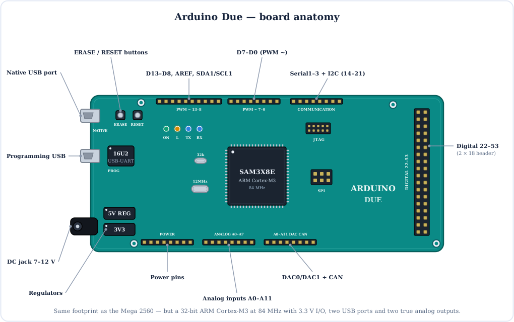
The Brain: SAM3X8E ARM Cortex-M3
The SAM3X8E (originally Atmel, now Microchip) is a 32-bit ARM Cortex-M3. Compared with the Uno's ATmega328P it runs 5× faster, handles 32-bit numbers in one instruction, and has 16× the flash and 48× the RAM.
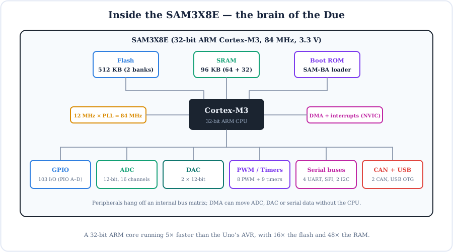
- Flash (512 KB, two 256 KB banks) — all of it is yours; the bootloader lives in a separate ROM.
- SRAM (96 KB, 64 KB + 32 KB) — room for large arrays, audio buffers and display frame data.
- SAM-BA boot ROM — a bootloader burned into the chip, so it can never be erased by accident.
- No EEPROM — unlike AVR boards; save settings to an SD card, external EEPROM or a flash library instead.
- Peripherals — 12-bit ADC, two 12-bit DACs, 8-channel PWM, 9 timer channels, four UARTs, SPI, two TWI (I2C), two CAN controllers, USB OTG and DMA.
Full Arduino Due Pinout
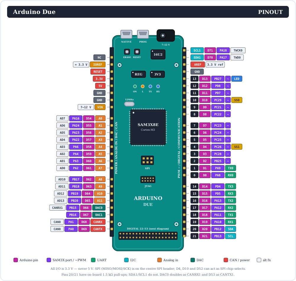
Here is the complete Arduino Due pinout. Each header pin shows its Arduino number, its SAM3X8E port (PAx/PBx/PCx/PDx) and its alternate functions: PWM, UART, I2C, ADC channel, DAC, CAN and SPI chip-select.
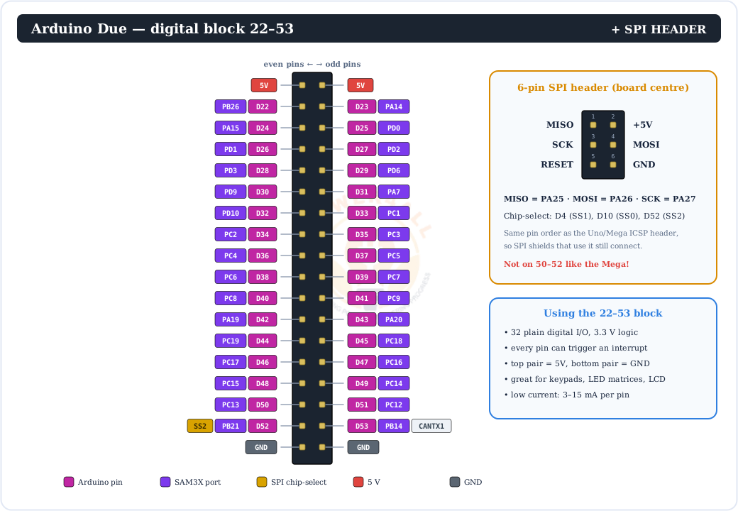
The big 2 × 18 block at the end of the board carries digital pins 22–53. The centre SPI header is also shown here, because on the Due SPI is only available there:
Prefer the short version? These cards summarise every pin group and how many there are:
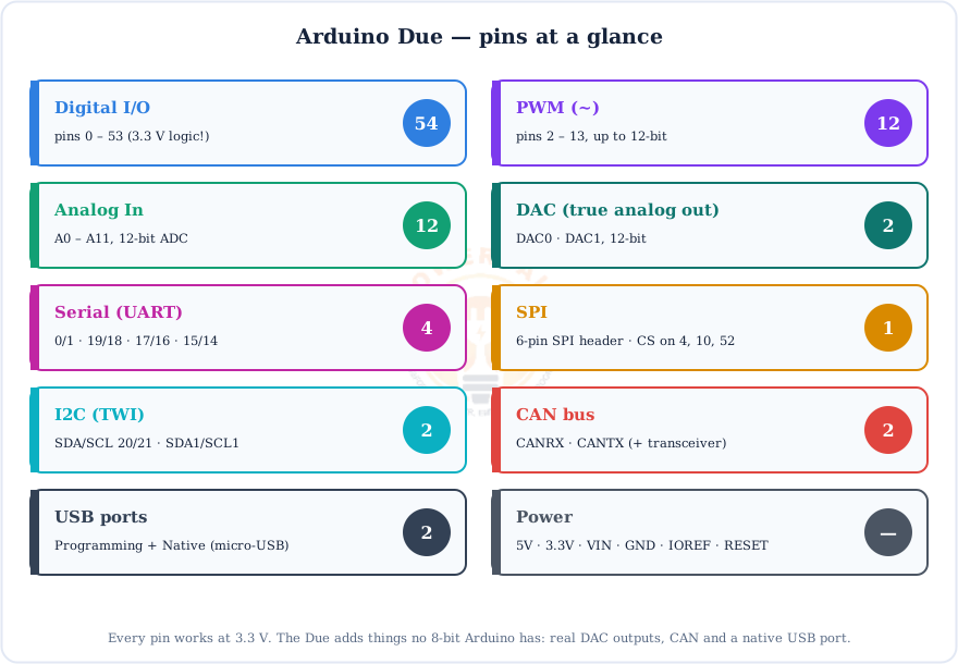
Every Pin Explained
Now let's go through each group of pins and what it does. The layout matches the Mega 2560, but several functions sit on different pins, so the differences are called out below.
Digital pins (0–53)
54 general-purpose pins driven with pinMode(), digitalWrite() and digitalRead(). HIGH is 3.3 V, not 5 V. Each pin can only supply a small current (about 3–15 mA depending on the pin), and all pins together are limited to 130 mA, so drive LEDs gently and use a transistor or MOSFET for anything bigger. On the Due every digital pin can be an interrupt with attachInterrupt().
PWM (~): 12 pins
Pins 2–13. analogWrite() at about 1 kHz, 8-bit by default or up to 12-bit.
Interrupts: all pins
Unlike the Uno (2 pins) or Mega (6), any Due pin can trigger attachInterrupt().
SPI
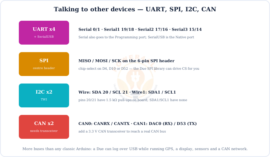
MISO/MOSI/SCK are only on the 6-pin SPI header. Chip-selects: D4, D10, D52.
Two I2C buses
20 = SDA, 21 = SCL (Wire, 1.5 kΩ pull-ups) and SDA1/SCL1 (Wire1, no pull-ups).
Pin 13
Drives the on-board “L” LED (LED_BUILTIN), handy for a first test.
Pins 4 & 10
Each is wired to two SAM3X pins (PC26+PA29, PC29+PA28) so they also work as SPI chip-selects.
Serial (UART): four ports + SerialUSB
| Port | RX / TX pins | Typical use |
|---|---|---|
| Serial | 0 (RX0) / 1 (TX0) | Programming USB port & Serial Monitor |
| Serial1 | 19 (RX1) / 18 (TX1) | GPS, GSM, another MCU |
| Serial2 | 17 (RX2) / 16 (TX2) | Bluetooth (3.3 V modules) |
| Serial3 | 15 (RX3) / 14 (TX3) | RS-485 or a second board |
| SerialUSB | Native USB port | Fast USB serial, independent of pins 0/1 |
Analog inputs (A0–A11)
12 analog inputs on a 12-bit ADC. They read 0–3.3 V as 0–1023 by default (for Uno compatibility) or as 0–4095 after analogReadResolution(12). They double as digital pins 54–65. The ADC reference is fixed at 3.3 V; the AREF pin is tied to it on the board.
DAC0 & DAC1: true analog outputs
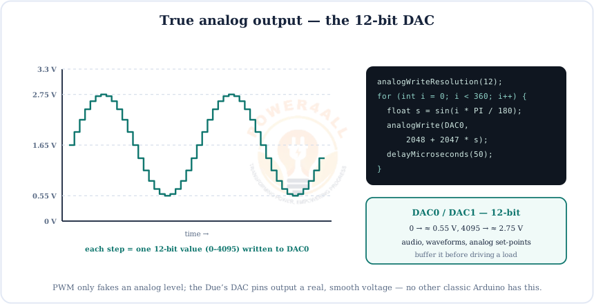
Two 12-bit digital-to-analog converters at the end of the analog header. analogWrite(DAC0, value) sets a real, steady voltage from roughly 0.55 V to 2.75 V. There is more on this in the DAC section.
CANRX & CANTX
The logic-level pins of the SAM3X8E's CAN0 controller. A second controller, CAN1, sits on DAC0 (RX) and D53 (TX). Both need an external 3.3 V CAN transceiver to join a real bus.
Power & special pins
| Pin | What it does |
|---|---|
| VIN | Raw input: 7–12 V recommended (6–16 V limit) to power the board. |
| 5V | Regulated 5 V output for modules, up to about 800 mA. Not a logic level for the Due's pins. |
| 3.3V | Regulated 3.3 V output, up to about 800 mA. The chip's own supply rail. |
| GND | Ground (0 V), found in several places around the board. |
| IOREF | Reads 3.3 V, so smart shields can tell this is a 3.3 V board. |
| RESET | Pull LOW to restart the sketch (same as the RESET button). |
| AREF | Tied to 3.3 V on the Due; the ADC reference is fixed. |
| ERASE button | Wipes the flash so the SAM-BA ROM takes over (a recovery tool). |
| JTAG header | 10-pin debug port for hardware debuggers (step through code, breakpoints). |
Coming from the Mega? Three gotchas
SPI is not on 50–53; it is only on the 6-pin SPI header. The board is 3.3 V, so many 5 V shields and modules need level shifting. And there's no EEPROM, so EEPROM.h sketches won't work unchanged.
The 3.3 V Logic Rule (Read This First)
This is the most important thing to know about the Due: its pins are 3.3 V and are not 5 V tolerant. A 5 V signal on any pin can permanently damage the SAM3X8E. Here is how to connect 5 V parts safely.
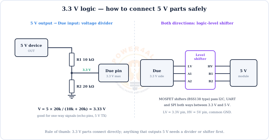
Voltage divider: Vout = Vin × R2 / (R1 + R2) = 5 V × 20 k / (10 k + 20 k) ≈ 3.33 V
- 3.3 V sensors and modules (most modern I2C/SPI sensors, ESP modules, SD cards): connect directly.
- 5 V outputs into the Due (HC-SR04 echo, 5 V UART TX): use a resistor divider or a shifter.
- Due outputs into 5 V inputs: 3.3 V HIGH is often but not always enough; a level shifter makes it reliable.
- Analog sensors powered at 5 V can output up to 5 V, so power them from 3.3V or divide the signal.
Powering the Due
The Due takes 5 V from either USB port, or 7–12 V from the DC jack or VIN. A switching regulator makes 5 V, and a second regulator makes the 3.3 V that the SAM3X8E and every I/O pin run on.
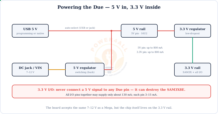
Pins are signals, not power outlets
The 5V and 3.3V pins can each supply a few hundred mA to modules, but the I/O pins together only give about 130 mA. Motors, servos and LED strips need their own supply with a common ground.
The Two USB Ports: Programming vs Native
The Due has two micro-USB ports. They look the same but connect to the chip in completely different ways.
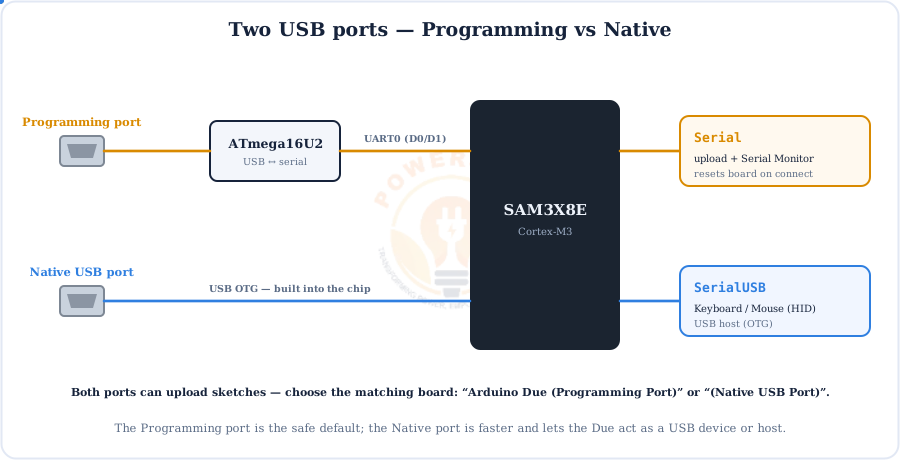
Serial); the Native port goes straight into the SAM3X8E (SerialUSB).| Programming port | Native USB port | |
|---|---|---|
| Location | Next to the DC jack | Next to the RESET button |
| Path | ATmega16U2 → UART0 (pins 0/1) | Direct to SAM3X8E USB OTG |
| In code | Serial | SerialUSB |
| Opening the port | Resets the board | Does not reset the sketch |
| Extras | Most reliable for uploads | Keyboard/Mouse HID, USB host, faster |
| IDE board | Arduino Due (Programming Port) | Arduino Due (Native USB Port) |
PWM Output (~)
PWM fakes an analog voltage by switching a pin on and off quickly. The Due has 12 PWM pins (2–13) swinging 0–3.3 V, with resolution up to 12 bits.
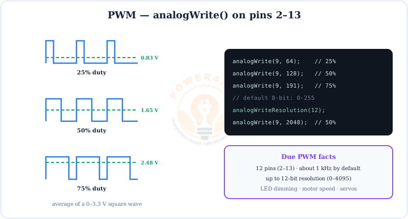
analogWriteResolution(12) for 0–4095 steps.// smooth 12-bit LED fade on PWM pin 9 void setup() { analogWriteResolution(12); } void loop() { for (int v = 0; v <= 4095; v += 8) { analogWrite(9, v); delayMicroseconds(500); } for (int v = 4095; v >= 0; v -= 8) { analogWrite(9, v); delayMicroseconds(500); } }
Analog Input: the 12-bit ADC
The Due's 12 analog inputs feed a 12-bit ADC: 4096 steps across 0–3.3 V, about 0.8 mV per step, four times finer than the Uno's 10-bit ADC. Work out other resolutions with the ADC Resolution Calculator.
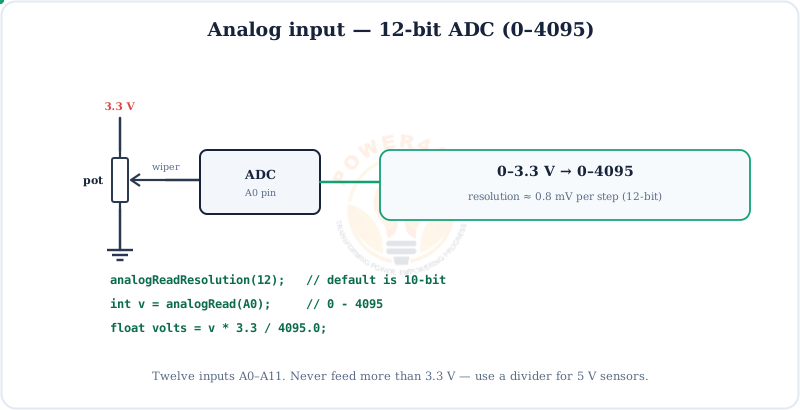
v * 3.3 / 4095.0.// read all 12 analog inputs at full 12-bit resolution void setup() { Serial.begin(115200); analogReadResolution(12); } void loop() { for (int i = 0; i < 12; i++) { Serial.print(analogRead(A0 + i)); Serial.print(' '); } Serial.println(); delay(250); }
DAC: True Analog Output
This is something no Uno, Nano or Mega can do. DAC0 and DAC1 output a real, smooth analog voltage rather than a PWM square wave, with 12-bit resolution, so the Due can generate audio and waveforms directly.
Treat the DAC pins gently
The DAC outputs are delicate. Never short them or connect them straight to a speaker or low-impedance load. Buffer them with an op-amp or an audio amplifier module.
Communication: UART, SPI, I2C & CAN
The Due has more buses than any classic Arduino: four UARTs plus SerialUSB, SPI, two I2C buses and two CAN controllers.
CAN bus
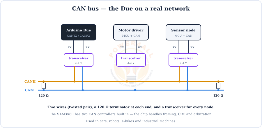
CAN is the rugged two-wire network used in cars, e-bikes, robots and industrial machines. The SAM3X8E handles the CAN protocol in hardware; add a 3.3 V CAN transceiver (such as an SN65HVD230 module) and 120 Ω terminators at both ends of the bus.
How Code Gets onto the Due
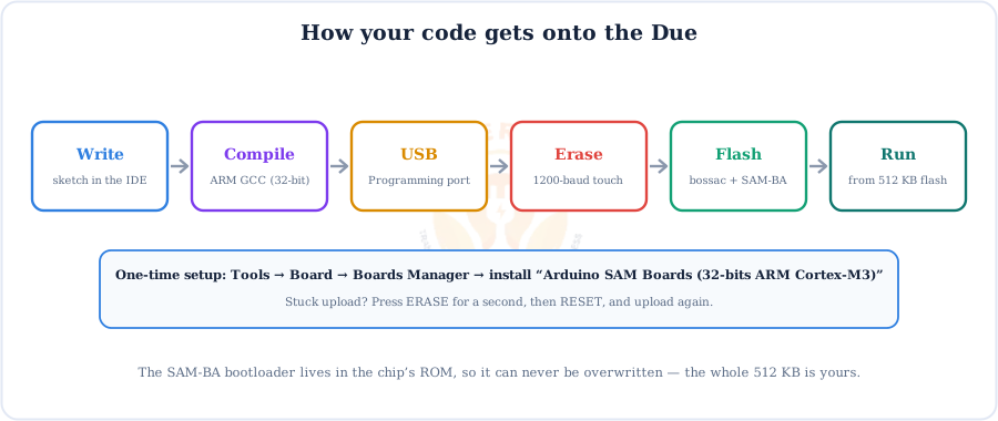
Uploading works differently from AVR boards. The IDE first erases the flash with a “1200-baud touch”, then bossac writes your program through the SAM-BA boot ROM.
First time? Install the SAM core
Open Tools → Board → Boards Manager, install Arduino SAM Boards (32-bits ARM Cortex-M3), then choose Arduino Due (Programming Port). If an upload fails with “No device found”, hold ERASE for a second, press RESET, and upload again.
Due vs Mega 2560 vs Uno
The Due and Mega 2560 share a board shape and pin count, but inside they are very different machines.
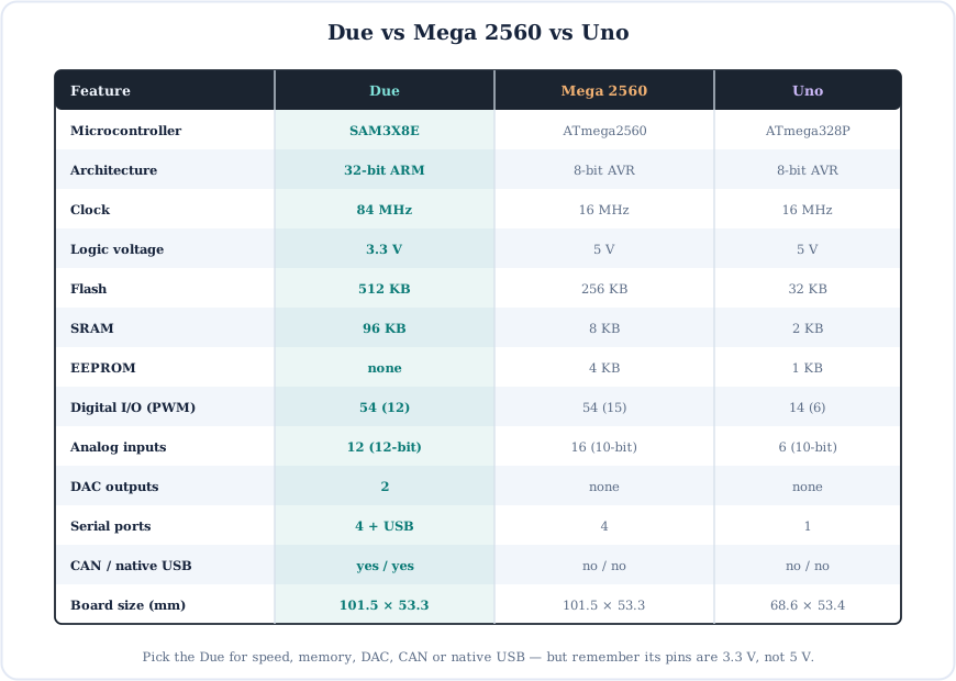
Choose the Due for speed, audio/DSP, the DAC, CAN, native USB or big memory. Choose the Mega for 5 V shields and modules, EEPROM or 16 analog inputs. Choose the Uno for learning. Need Wi-Fi? Look at the ESP32.
Code Examples
Standard Arduino code runs unchanged. These examples also use the Due's own features: 12-bit I/O, the DAC and SerialUSB.
1. Blink the on-board LED
void setup() {
  pinMode(LED_BUILTIN, OUTPUT);       // pin 13
}
void loop() {
  digitalWrite(LED_BUILTIN, HIGH);
  delay(1000);
  digitalWrite(LED_BUILTIN, LOW);
  delay(1000);
}
2. Output a steady analog voltage on DAC0
void setup() {
  analogWriteResolution(12);          // 0-4095
  analogWrite(DAC0, 2048);            // about 1.65 V, mid-scale
}
void loop() {}
3. Print over the Native USB port
void setup() {
  SerialUSB.begin(115200);            // Native port (baud is ignored, it's full-speed USB)
  while (!SerialUSB);                 // wait for the PC to open the port
}
void loop() {
  SerialUSB.println(millis());
  delay(500);
}
4. Interrupt on any pin
volatile int presses = 0;
void onPress() { presses++; }
void setup() {
  Serial.begin(115200);
  pinMode(30, INPUT_PULLUP);                               // any Due pin works
  attachInterrupt(digitalPinToInterrupt(30), onPress, FALLING);
}
void loop() { Serial.println(presses); delay(500); }
Beginner Mini-Projects
Four complete projects. The first works on any Arduino; the others show off what makes the Due special.
Project 1: Blink an LED
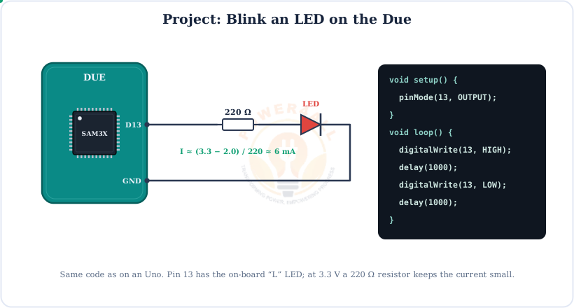
void setup() { pinMode(13, OUTPUT); }
void loop() {
  digitalWrite(13, HIGH); delay(500);
  digitalWrite(13, LOW);  delay(500);
}
Project 2: DAC sine-wave generator
const int N = 100;
uint16_t table[N];
void setup() {
  analogWriteResolution(12);
  for (int i = 0; i < N; i++)
    table[i] = 2048 + 2047 * sin(2 * PI * i / N);
}
void loop() {
  for (int i = 0; i < N; i++) {
    analogWrite(DAC0, table[i]);
    delayMicroseconds(10);                   // sets the frequency
  }
}
Project 3: 12-bit precision voltmeter
void setup() { Serial.begin(115200); analogReadResolution(12); }
void loop() {
  long sum = 0;
  for (int i = 0; i < 64; i++) sum += analogRead(A0);  // average 64 samples
  float volts = (sum / 64.0) * 3.3 / 4095.0;
  Serial.print(volts, 4); Serial.println(" V");
  delay(300);
}
Project 4: USB keyboard button (Native port)
#include <Keyboard.h>
void setup() { pinMode(2, INPUT_PULLUP); Keyboard.begin(); }
void loop() {
  if (digitalRead(2) == LOW) {
    Keyboard.println("Hello from Arduino Due!");
    delay(500);                                // simple debounce
  }
}
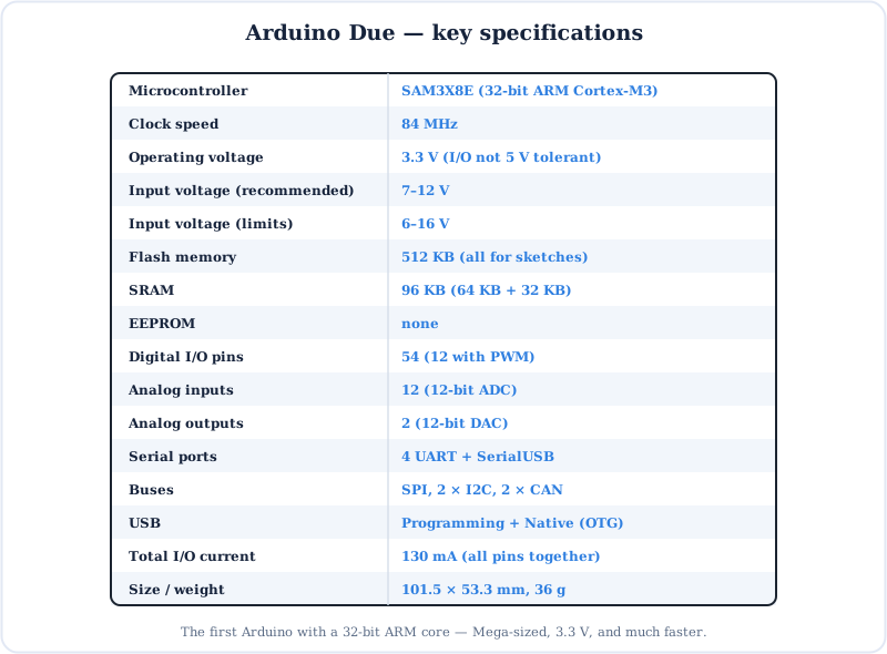
Specifications
The Arduino Due at a glance.
Key Terms — Glossary
| Term | Meaning |
|---|---|
| ARM Cortex-M3 | A 32-bit processor core designed for microcontrollers; the heart of the SAM3X8E. |
| SAM3X8E | The Due's microcontroller: 84 MHz, 512 KB flash, 96 KB SRAM. |
| 3.3 V logic | HIGH = 3.3 V. Due pins must never see 5 V. |
| Level shifter | A circuit that translates signals between 3.3 V and 5 V. |
| DAC | Digital-to-analog converter; DAC0/DAC1 output a real voltage. |
| ADC | Analog-to-digital converter; 12-bit on the Due (0–4095). |
| PWM (~) | Pulse-width modulation; pins 2–13 on the Due. |
| SerialUSB | The serial port of the Native USB connector. |
| CAN | Controller Area Network: a robust 2-wire bus used in vehicles and machines. |
| SAM-BA / bossac | The boot ROM and the PC tool that together write sketches to flash. |
| JTAG | A debug interface for stepping through code with a hardware debugger. |
| DMA | Direct memory access: moves data between peripherals and RAM without the CPU. |
Frequently Asked Questions
Quick answers to the questions people ask most about the Arduino Due.
What is the Arduino Due?
The first Arduino with a 32-bit ARM core: a SAM3X8E Cortex-M3 at 84 MHz with 512 KB flash and 96 KB SRAM. It has 54 digital pins (12 PWM), 12 analog inputs, 2 DAC outputs, four UARTs, SPI, two I2C buses, CAN and two USB ports, all at 3.3 V logic, on the Mega 2560's footprint.
Is the Arduino Due 5 V tolerant?
No. The Due runs at 3.3 V and its pins are not 5 V tolerant. More than 3.3 V on any pin can permanently damage the SAM3X8E. Use a voltage divider or logic-level shifter for 5 V sensors and modules.
How many pins does the Arduino Due have?
54 digital I/O pins (0–53), with PWM on 2–13; 12 analog inputs (A0–A11); DAC0 and DAC1; CANRX/CANTX; SDA1/SCL1; a 6-pin SPI header; a JTAG header; and power pins 5V, 3.3V, VIN, GND, IOREF, RESET and AREF.
What microcontroller does the Arduino Due use?
The SAM3X8E, a 32-bit ARM Cortex-M3 at 84 MHz with 512 KB flash (two banks), 96 KB SRAM, a SAM-BA boot ROM, DMA, a 12-bit ADC, two 12-bit DACs, PWM and timers, four UARTs, SPI, two TWI (I2C), two CAN controllers and USB OTG.
What is the difference between the Programming and Native USB ports on the Due?
The Programming port goes through an ATmega16U2 to UART0, so it appears as Serial and resets the board when opened. The Native port connects straight to the SAM3X8E's USB controller: it appears as SerialUSB, is faster, and lets the Due act as a USB keyboard, mouse or host. Both can upload sketches.
How do I program the Arduino Due?
Install Arduino SAM Boards (32-bits ARM Cortex-M3) in the Boards Manager, connect the Programming port, choose Arduino Due (Programming Port) and the COM port, and click Upload. The IDE erases the flash and bossac writes the sketch through the SAM-BA ROM. If it gets stuck, press ERASE, then RESET, and retry.
Does the Arduino Due have a DAC?
Yes, two 12-bit DAC outputs: DAC0 and DAC1. They produce a true analog voltage from about 0.55 V to 2.75 V. Use analogWriteResolution(12) and analogWrite(DAC0, 0–4095) for audio, sine waves or analog set-points.
Arduino Due vs Mega 2560: which should I use?
Both have 54 digital pins and the same board shape. Choose the Due for speed (84 MHz 32-bit ARM vs 16 MHz 8-bit AVR), more memory, the DAC, CAN, native USB or 12-bit analog. Choose the Mega for 5 V logic, EEPROM, 16 analog inputs or full compatibility with 5 V shields and AVR libraries.
Conclusion & Key Takeaways
The Arduino Due brings 32-bit ARM power to the familiar Arduino workflow. It is Mega-sized, much faster, and full of features the 8-bit boards lack. Just remember that it runs at 3.3 V.
SAM3X8E
32-bit ARM, 84 MHz.
3.3 V only
Never 5 V on a pin.
54 + 12 pins
12 PWM, 12-bit ADC.
2 DAC
True analog out.
2 USB ports
Serial + SerialUSB.
CAN + SPI header
SPI not on 50–53.