What are Pulse & PWM Signals?
The complete guide to pulse and pulse width modulation (PWM) signals — the on/off waveform that controls motors, LEDs, heaters and power supplies. From pulse anatomy and duty cycle (D = ton/T) to average voltage, how PWM is generated (SPWM) and where it is used.
Complete Learning Path — Pulse & PWM Signals
From pulse anatomy and duty cycle, to PWM, average voltage, SPWM generation, frequency, types and real-world uses
What are Pulse & PWM Signals?
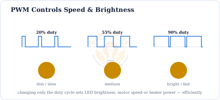
A pulse signal is a waveform that jumps between two levels — usually OFF (0) and ON (high) — staying at each for a set time. A repeating series of pulses is a pulse train. Pulse Width Modulation (PWM) takes this idea further: it switches the power ON and OFF very fast and varies the width of the ON pulses to control the average power delivered to a load.
PWM is one of the most important techniques in power electronics and embedded systems. It lets a simple digital ON/OFF switch behave like a smooth, adjustable analog control — setting motor speed, LED brightness, or heater power — with almost no wasted energy.

Switch, don’t throttle
Instead of throttling power with a resistor (which wastes energy as heat), PWM chops the full supply into pulses. The load responds to the average, so you get precise control with high efficiency.
Anatomy of a Pulse
Every pulse train is described by a handful of parameters. Get these clear and the rest of PWM follows easily.
Amplitude
The height of the pulse — the HIGH level (e.g. 5 V or 12 V) above the LOW level.
Period (T)
Time for one full ON+OFF cycle. Linked to frequency by T = 1/f.
On-time (ton)
Also called pulse width — how long the pulse stays HIGH each period.
Off-time (toff)
How long it stays LOW. Note T = ton + toff.
T = ton + toff · f = 1 / T
Period is on-time plus off-time; frequency is the number of pulses per second
Duty Cycle: D = ton / T
The duty cycle is the fraction of each period the pulse is HIGH. It is the master control knob of PWM — change it and you change the delivered power.
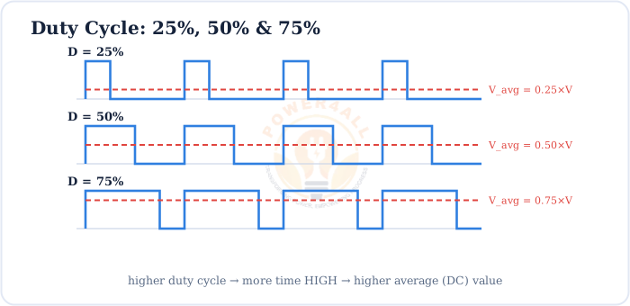
D = ton / T = ton / (ton + toff)
Duty cycle as a fraction (0 to 1) or ×100 for a percentage
Worked example
A pulse is HIGH for ton = 2 ms and LOW for toff = 3 ms.
T = 2 + 3 = 5 ms, so D = 2/5 = 0.4 = 40%.
The frequency is f = 1/T = 1/0.005 = 200 Hz.
Mark-space ratio
Some textbooks use the mark-to-space ratio = ton : toff. A 50% duty cycle is a 1:1 mark-space ratio (a symmetric square wave).
What is Pulse Width Modulation (PWM)?
PWM keeps the frequency fixed and varies the duty cycle to set the average output. “Modulation” here simply means changing the pulse width in step with whatever value you want to deliver.
The core idea in one line
Switch fully ON and fully OFF, fast — then set the average anywhere between 0 and the supply by choosing how wide the ON pulses are.
Because the switching happens far faster than the load can respond, a motor, LED filament, heater or a simple RC filter “sees” only the smooth average, not the individual pulses.
PWM & Average Voltage
The whole point of PWM is that the average output voltage is proportional to the duty cycle. This is what turns a digital switch into an analog controller.
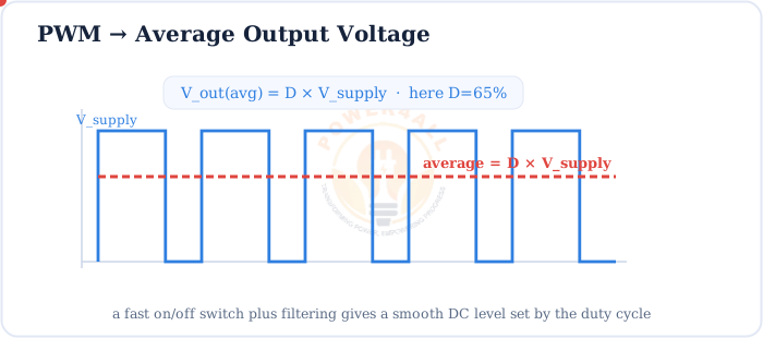
Vavg = D × Vin
Average (DC) output voltage from duty cycle D and supply voltage Vin
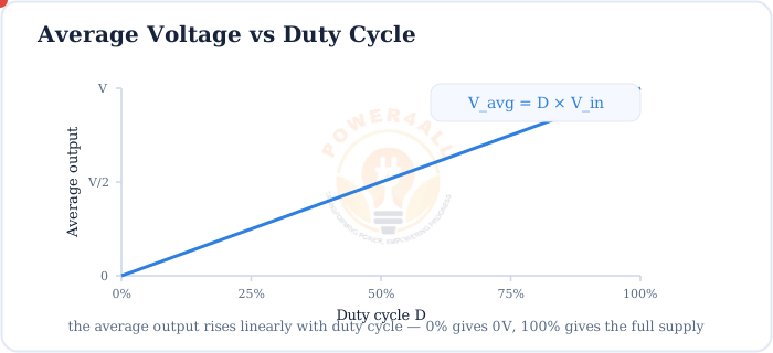
Worked example
A 12 V supply is switched with a D = 75% PWM signal:
Vavg = 0.75 × 12 = 9 V — the load behaves as if fed 9 V DC.
How PWM is Generated (SPWM)
The classic way to make PWM is to compare a reference signal with a triangular carrier. The output goes HIGH whenever the reference is above the carrier.
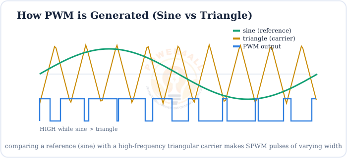
When the reference is a steady DC level you get constant-duty PWM; when it is a sine wave you get Sinusoidal PWM (SPWM), the technique inverters use to synthesise smooth AC from a DC bus.
m = Vreference / Vcarrier
Modulation index m — how far the reference fills the carrier (0 to 1 for linear PWM)
Microcontrollers (Arduino, STM32, ESP32) do this digitally with a counter and a compare register — and you can size SPWM duty values with the SPWM Duty Cycle Calculator.
PWM Frequency & Resolution
Two settings define a PWM channel: the frequency (how fast it switches) and the resolution (how finely you can set the duty cycle).
| Parameter | What it is | Trade-off |
|---|---|---|
| Frequency | Pulses per second (fixed) | Higher = smoother & quieter, but more switching loss |
| Duty cycle | Fraction HIGH (varied) | Sets the average output 0–100% |
| Resolution | Number of duty steps (bits) | More bits = finer control, needs a faster clock |
Why frequency matters
Motor and LED PWM is often set above 20 kHz so the switching is above human hearing (no whine) and the ripple is easy to filter. Too low a frequency causes flicker or audible buzz.
Types of PWM
The same basic idea appears in several flavours, chosen to suit the load.
Standard PWM
Fixed frequency, variable duty. Used for DC motor speed, LED dimming, heaters.
SPWM
Sinusoidal PWM — duty varies as a sine. Core of AC inverters.
SVPWM
Space-vector PWM — smarter 3-phase inverter switching, better DC-bus use.
Unipolar / Bipolar
Whether the output swings 0↔+V or −V↔+V — matters in H-bridges.
Where PWM is Used
PWM is everywhere efficient control is needed — from a 3 mm LED to a megawatt drive.
LED dimming
Brightness & RGB colour mixing without changing LED colour temperature.
SMPS & converters
Buck, boost and other DC-DC converters regulate output by duty cycle.
Inverters
SPWM turns DC into clean AC for solar, UPS and motor drives.
Servos & ESCs
Pulse width sets servo angle and electronic-speed-controller throttle.
Class-D audio
Audio encoded as PWM then filtered — efficient, cool-running amplifiers.
Advantages of PWM
PWM wins because it controls power by switching, not by dissipating.
High efficiency
Switch is fully on or off — little power wasted as heat.
Precise control
Fine, repeatable control of speed, brightness or voltage.
Digital-friendly
Generated directly by microcontrollers — no DAC needed.
Robust & cheap
Simple switches, low heat, small heatsinks, long life.
Key Terms at a Glance
The essential pulse & PWM vocabulary students and engineers search for.
Pulse train
A repeating series of ON/OFF pulses.
Duty cycle (D)
ton/T; fraction of time HIGH.
Pulse width
The on-time ton of each pulse.
PWM
Pulse width modulation — vary duty at fixed f.
SPWM
Sinusoidal PWM — sine-shaped duty.
Modulation index
Reference ÷ carrier amplitude.
Frequently Asked Questions
Quick, expert answers to the questions people ask most about pulse & PWM signals.
What is PWM in simple words?
PWM (pulse width modulation) rapidly switches power ON and OFF and changes how long it stays ON each cycle. The load responds to the average, so a wider ON time means more power — a simple, efficient way to control speed, brightness or voltage.
What is the duty cycle formula?
D = ton / T, where ton is the on-time and T is the period (ton + toff). Multiply by 100 for a percentage.
What is the average voltage of a PWM signal?
Vavg = D × Vsupply. For example, a 5 V signal at 40% duty gives 2 V average; at 80% it gives 4 V.
How is PWM generated?
By comparing a reference signal with a high-frequency triangular carrier in a comparator. The output is HIGH whenever the reference exceeds the carrier. A sine reference gives sinusoidal PWM (SPWM). Microcontrollers do the same with a timer/counter and a compare value.
What is the difference between frequency and duty cycle?
Frequency is how many pulses per second (fixed); duty cycle is the fraction of each pulse that is HIGH (varied). You change duty to control power and pick frequency for smoothness and low noise.
Why is PWM efficient?
The switch is either fully ON (almost no voltage across it) or fully OFF (almost no current), so it dissipates very little power. Unlike a series resistor, PWM does not burn the unwanted power as heat.
What is SPWM?
Sinusoidal PWM — PWM whose duty cycle varies as a sine wave. Made by comparing a sine reference with a triangular carrier, it is how inverters build a smooth sine-like AC output from DC.
Is a PWM signal digital or analog?
The signal itself is digital (two levels), but by varying its duty cycle and filtering it, PWM represents and delivers an analog average — a cheap digital-to-analog technique.
What frequency should PWM be?
It depends on the load. LED and motor PWM is often above 20 kHz to avoid audible whine and visible flicker; slow heaters can use a few Hz. Higher frequency is smoother but increases switching losses.
What is PWM used for?
Motor speed control, LED dimming and RGB mixing, servo/ESC control, heaters and fans, class-D audio, DC-DC converters and SMPS, and inverters that create AC from DC.
Conclusion & Key Takeaways
Pulse & PWM signals turn a simple ON/OFF switch into a precise, efficient power controller — the workhorse of modern electronics.
Pulse train
ON/OFF waveform, period T.
D = ton/T
Duty cycle = control knob.
Vavg = D×Vin
Average set by duty.
Sine vs triangle
Comparator makes PWM/SPWM.
Fixed f, vary D
Frequency stays, duty changes.
Efficient control
Motors, LEDs, SMPS, inverters.