Arduino Leonardo
The Arduino that can pretend to be a keyboard or mouse. The Arduino Leonardo uses the ATmega32U4 with native USB built in, so it needs no separate USB chip and can appear to your PC as a real USB device. This guide covers the full board anatomy, a complete pinout with every pin explained, its native-USB HID trick, the buses, a Leonardo vs Uno comparison, and code and mini-projects.
Complete Learning Path — Arduino Leonardo
From board anatomy and the ATmega32U4, to a full pinout with every pin detailed, power, digital & analog I/O, native USB (HID), the buses, uploading, Leonardo vs Uno, code and mini-projects
What is the Arduino Leonardo?
The Arduino Leonardo looks like an Uno, but its brain is the ATmega32U4 — a chip with USB built right in. That single change means the board needs no separate USB-serial chip, and it can pretend to be a USB keyboard or mouse.
Everything else is Uno-familiar: 5 V logic, the same shield shape and the same Arduino IDE. Just a few pins move around (more on that below).
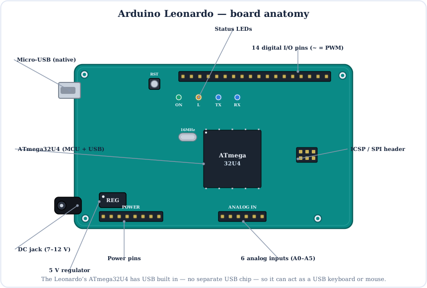
The Brain: ATmega32U4
The ATmega32U4 is the same family as the Uno's chip, but with one big addition: a built-in USB controller. It runs at 16 MHz and carries a little more RAM.
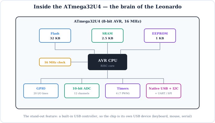
- Flash (32 KB) — stores your program; ~4 KB is the (larger, USB) bootloader.
- SRAM (2.5 KB) — working memory for variables.
- EEPROM (1 KB) — non-volatile store that survives power-off.
- Native USB — the stand-out feature: the chip is its own USB device (keyboard, mouse, or serial).
Full Arduino Leonardo Pinout
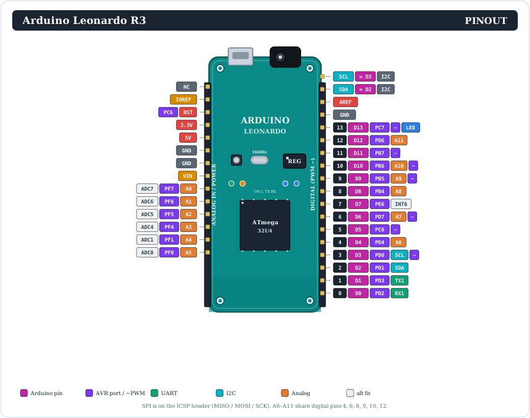
Here is the complete pinout. The header shape matches the Uno, but note the differences: I2C is on D2/D3, SPI is on the ICSP header, and six analog inputs (A6–A11) live on digital pins.
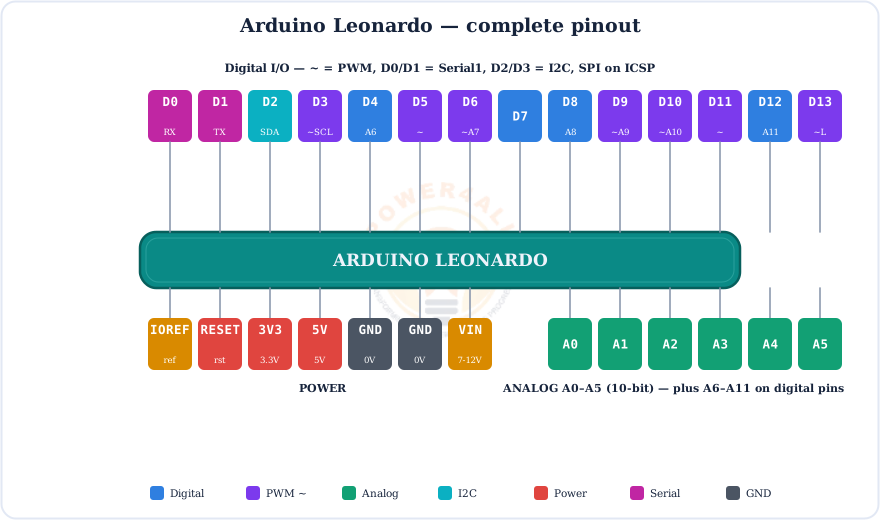
Prefer a simpler view? This colour-coded map groups the header pins by function:
Every Pin Explained
Let's go through each group of pins. Where the Leonardo differs from the Uno, it's flagged — those differences trip up a lot of beginners.
Digital pins (0–13)
14 header pins that read or write HIGH (5 V) or LOW (0 V) with pinMode(), digitalWrite() and digitalRead(). Each handles ~20 mA (40 mA max). The A0–A5 pins can also be used as digital, giving 20 in total.
D2 (SDA) & D3 (SCL)
The I2C bus — on the Leonardo it's here, not on A4/A5.
D0 (RX) & D1 (TX)
Serial1 hardware UART — separate from the USB Serial.
PWM (~) — 7 pins
Pins 3, 5, 6, 9, 10, 11, 13 — analogWrite(0–255).
Interrupts
Pins 0, 1, 2, 3, 7 support attachInterrupt().
Pin 13
Wired to the on-board “L” LED — a first test with no extra parts.
Analog input pins (12 total)
The Leonardo has 12 analog inputs, each a 10-bit ADC reading 0–5 V as 0–1023:
- A0–A5 on the analog header.
- A6–A11 share digital pins 4, 6, 8, 9, 10, 12 — read them with
analogRead(A6)…analogRead(A11).
The buses (and where they moved)
| Bus | Leonardo pins | On the Uno… |
|---|---|---|
| Serial (USB) | Serial — virtual USB port | same object as pins 0/1 |
| UART | Serial1 on D0 (RX) / D1 (TX) | this is Serial |
| I2C | D2 (SDA) / D3 (SCL) | A4 / A5 |
| SPI | ICSP header only | 11–13 + ICSP |
Power pins
VIN (7–12 V in), 5V (regulated out), 3.3V (~50 mA), GND, IOREF, RESET and AREF — the same as the Uno.
The classic Leonardo trap
If a library or tutorial says “I2C on A4/A5” or “SPI on 11–13”, that's Uno wiring. On the Leonardo, wire I2C to 2/3 and take SPI from the ICSP header. And use Serial1 (not Serial) for a module on pins 0/1.
Native USB — Keyboard & Mouse (HID)
This is why the Leonardo exists. Because the 32U4 speaks USB itself, the board can present to a PC as a real USB keyboard or mouse — something the Uno and Nano can't do.
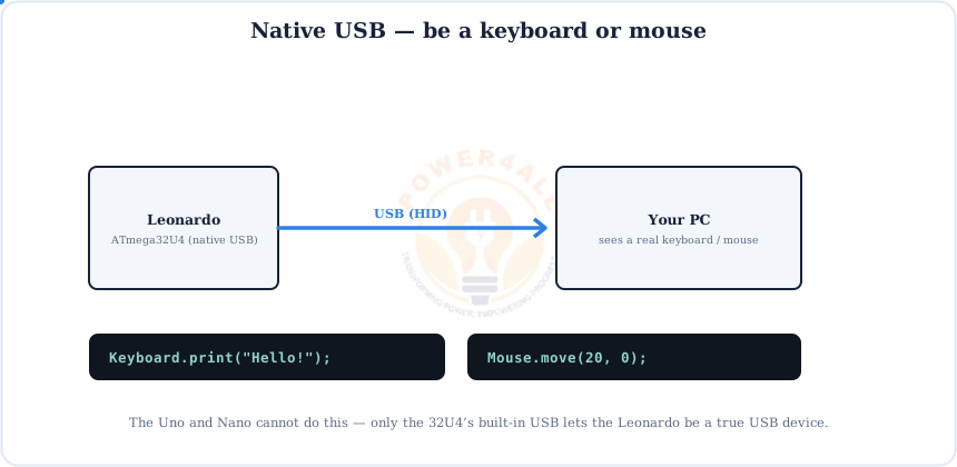
Keyboard.print(), move the cursor with Mouse.move().// type a line when a button on pin 2 is pressed #include <Keyboard.h> void setup() { pinMode(2, INPUT_PULLUP); Keyboard.begin(); } void loop() { if (digitalRead(2) == LOW) { // pressed Keyboard.println("Hello from Leonardo!"); delay(1000); // avoid repeats } }
Gate your HID code
A sketch that types or moves the mouse non-stop makes the PC very hard to use. Always trigger HID actions from a button or condition (as above), never on every loop(). If you get stuck, double-tap RESET to re-flash.
Powering the Leonardo
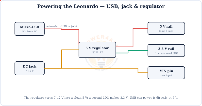
Power it from micro-USB (5 V), a 7–12 V DC jack, or the VIN pin. An on-board regulator makes the clean 5 V the chip needs.
Digital I/O
Output a HIGH/LOW to drive an LED or relay, or read a HIGH/LOW input from a button or sensor.
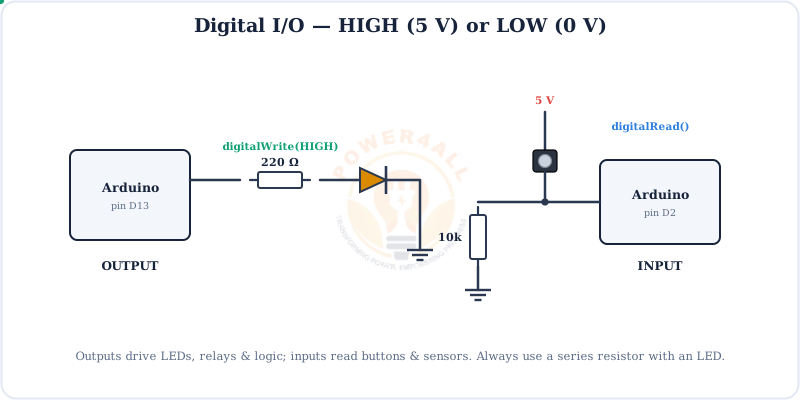
// digital output + input
void setup() {
  pinMode(13, OUTPUT);      // LED pin
  pinMode(7, INPUT);        // button pin
}
void loop() {
  digitalWrite(13, digitalRead(7));   // LED follows the button
}
PWM Output (~)
PWM fakes an analog voltage by switching a pin on and off fast. The Leonardo has 7 PWM pins: 3, 5, 6, 9, 10, 11, 13.
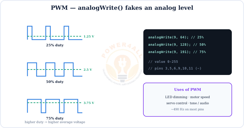
analogWrite(pin, 0–255) on any of the 7 ~ pins.// fade an LED on a PWM pin (~9) void setup() { pinMode(9, OUTPUT); } void loop() { for (int v = 0; v <= 255; v++) { analogWrite(9, v); delay(5); } for (int v = 255; v >= 0; v--) { analogWrite(9, v); delay(5); } }
Analog Input (ADC)
The Leonardo has 12 analog inputs — six more than the Uno. Each 10-bit reading turns 0–5 V into 0–1023.
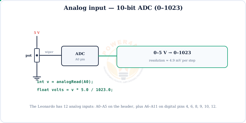
v * 5.0 / 1023.0. A6–A11 live on digital pins.// read an "extra" analog input (A6 is on digital pin 4) void setup() { Serial.begin(9600); } void loop() { int raw = analogRead(A6); // 0..1023 float volts = raw * 5.0 / 1023.0; Serial.println(volts); delay(200); }
Serial, SPI & I2C
The Leonardo has the usual three buses — but on different pins from the Uno, so it's worth a close look.
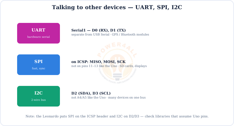
Serial), SPI on the ICSP header, I2C on D2/D3.How Code Gets onto the Leonardo
The 32U4 handles USB itself, so there's no separate USB chip in the upload path. Write a sketch, connect micro-USB, pick Arduino Leonardo, and upload.
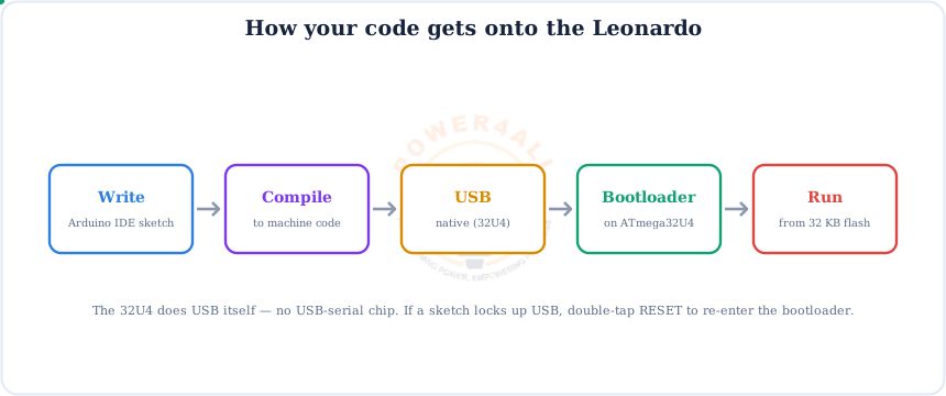
If an upload fails: double-tap RESET
Because the sketch shares the USB port, a bad sketch can hide the board. Double-tap the RESET button to force the bootloader for a few seconds, then upload and pick the temporary bootloader port.
Leonardo vs Uno
Same shape, same 5 V code — but the 32U4 changes what the board can do and where a few pins live.
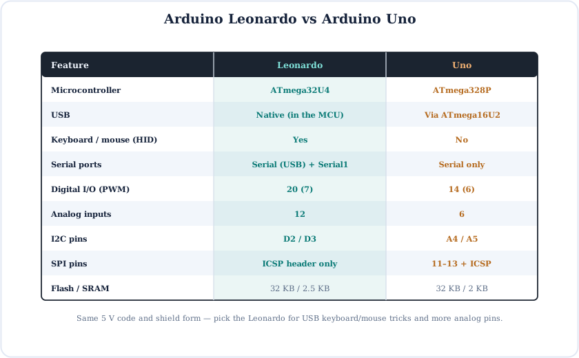
Choose the Leonardo for USB keyboard/mouse projects and more analog inputs; the Uno for the most tutorials, easiest uploads and the widest shield support.
Code Examples
The everyday building blocks — plus one that only the Leonardo can run.
1. Blink the on-board LED
void setup() { pinMode(LED_BUILTIN, OUTPUT); }
void loop() {
  digitalWrite(LED_BUILTIN, HIGH); delay(1000);
  digitalWrite(LED_BUILTIN, LOW);  delay(1000);
}
2. Print to the Serial Monitor (wait for USB)
void setup() {
  Serial.begin(9600);
  while (!Serial) { ; }          // wait for the USB port (Leonardo)
  Serial.println("Ready!");
}
void loop() { Serial.println(millis()); delay(1000); }
3. Talk to a module on Serial1
void setup() {
  Serial.begin(9600);       // USB to PC
  Serial1.begin(9600);      // module on pins 0/1
}
void loop() {
  if (Serial1.available()) Serial.write(Serial1.read());
}
Beginner Mini-Projects
Start with the classics, then try the HID trick that makes the Leonardo special.
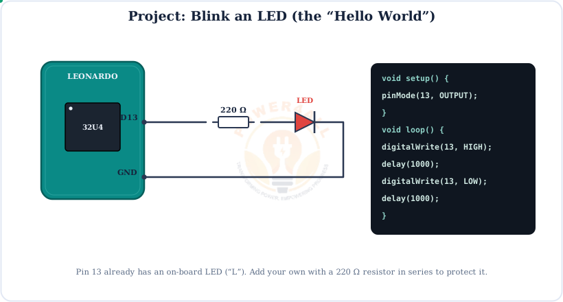
Project 1 — Blink an LED
void setup() { pinMode(13, OUTPUT); }
void loop() {
  digitalWrite(13, HIGH); delay(500);
  digitalWrite(13, LOW);  delay(500);
}
Project 2 — Button-triggered keyboard shortcut
#include <Keyboard.h>
void setup() { pinMode(2, INPUT_PULLUP); Keyboard.begin(); }
void loop() {
  if (digitalRead(2) == LOW) {
    Keyboard.print("power4all.in");
    delay(800);              // debounce / avoid repeats
  }
}
Project 3 — Mouse jiggler (button-gated)
#include <Mouse.h>
void setup() { pinMode(3, INPUT_PULLUP); Mouse.begin(); }
void loop() {
  if (digitalRead(3) == LOW) { Mouse.move(3, 0); delay(200); Mouse.move(-3, 0); delay(200); }
}
Project 4 — I2C sensor on D2/D3
Wire library.#include <Wire.h> void setup() { Serial.begin(9600); Wire.begin(); // SDA=2, SCL=3 on the Leonardo } void loop() { Wire.beginTransmission(0x3C); // example device address byte err = Wire.endTransmission(); Serial.println(err == 0 ? "found" : "not found"); delay(1000); }
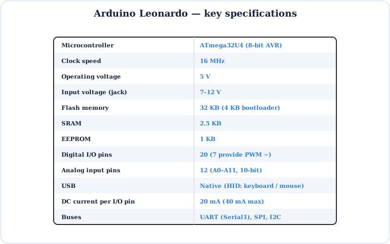
Specifications
The Arduino Leonardo at a glance.
Key Terms — Glossary
| Term | Meaning |
|---|---|
| ATmega32U4 | The Leonardo's 8-bit AVR chip, with a built-in USB controller. |
| Native USB | USB handled by the MCU itself — no separate USB-serial chip. |
| HID | Human Interface Device — a keyboard or mouse the PC recognises. |
| Serial vs Serial1 | Serial = USB to PC; Serial1 = hardware UART on 0/1. |
| PWM (~) | Pulse-width modulation; 7 pins on the Leonardo (3,5,6,9,10,11,13). |
| ADC | Analog-to-digital converter; 12 inputs, 10-bit (0–1023). |
| I2C | 2-wire bus on D2 (SDA) / D3 (SCL) — not A4/A5. |
| SPI | On the ICSP header (MISO/MOSI/SCK) — not pins 11–13. |
| Bootloader | USB bootloader; double-tap RESET to force it if uploads fail. |
Frequently Asked Questions
Quick answers to the questions people ask most about the Arduino Leonardo.
What is the Arduino Leonardo?
A board built around the ATmega32U4, which has native USB. It can act as a USB keyboard or mouse, and has 20 digital pins (7 PWM), 12 analog inputs, 32 KB flash and 5 V logic in the Uno's shield-compatible shape.
Leonardo vs Uno — what's different?
Native USB (so it can be a keyboard/mouse and needs no USB chip), 20 digital + 12 analog pins, I2C on D2/D3 (not A4/A5), SPI on the ICSP header only, and Serial (USB) separate from Serial1 (pins 0/1).
Can it really be a keyboard or mouse?
Yes — use the built-in Keyboard and Mouse libraries (Keyboard.print(), Mouse.move()). Always trigger HID actions from a button, or the PC becomes hard to control.
Where are I2C and SPI?
I2C is on pins 2 (SDA) and 3 (SCL). SPI is only on the ICSP header (MISO, MOSI, SCK) — not pins 11–13. Serial1 (UART) is on pins 0/1.
How many analog inputs does it have?
12: A0–A5 on the analog header, plus A6–A11 on digital pins 4, 6, 8, 9, 10 and 12. Read them with analogRead(A6) and so on.
What's the difference between Serial and Serial1?
Serial is the USB connection to the PC (the Serial Monitor). Serial1 is the hardware UART on pins 0/1. On the Uno these are the same; on the Leonardo they're separate objects.
Why won't my Leonardo upload?
A misbehaving sketch can hide the USB port. Double-tap the RESET button to force the bootloader for a few seconds, then start the upload and select the temporary bootloader port.
Do Uno shields fit the Leonardo?
Physically yes — same shape and headers. Just check shields that assume I2C on A4/A5 or SPI on 11–13, since the Leonardo puts those on 2/3 and the ICSP header.
Conclusion & Key Takeaways
The Arduino Leonardo is the Uno's USB-native cousin — same easy code, plus the power to be a keyboard or mouse.
ATmega32U4
Native USB built in.
Keyboard / mouse
HID libraries.
20 + 12 pins
Digital + analog.
I2C on 2/3
SPI on ICSP.
Serial + Serial1
USB and UART.
Uno-shaped
Shields fit.