Arduino Nano
All the power of the Uno, shrunk to fit a breadboard. The Arduino Nano runs the same 8-bit ATmega328P but adds two extra analog inputs and plugs straight into a breadboard. This guide covers the full board anatomy, a complete pinout with every pin explained, power & programming over mini-USB, a Nano vs Uno comparison, and finishes with code examples and mini-projects.
Complete Learning Path — Arduino Nano
From board anatomy and the ATmega328P, to a full pinout with every pin detailed, power, digital & analog I/O, the buses, uploading, Nano vs Uno, code and mini-projects
What is the Arduino Nano?
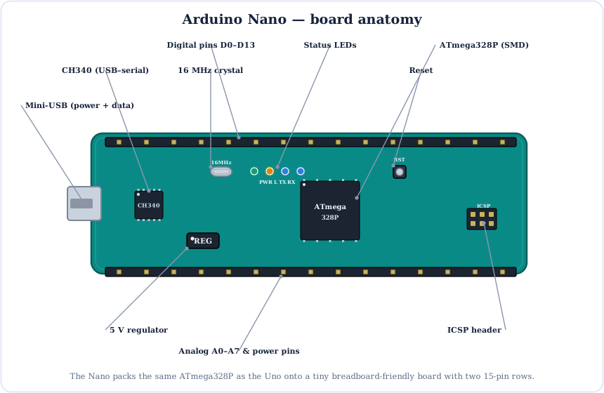
The Arduino Nano is a compact, breadboard-friendly microcontroller board built around the same 8-bit ATmega328P as the Arduino Uno. It packs that chip, a USB-serial bridge and two rows of pins onto a board barely bigger than a stick of gum.
You get the Uno's brain and 100% of its code compatibility, but small enough to drop straight into a breadboard or solder into a finished project.
The Brain: ATmega328P
The Nano uses the very same ATmega328P as the Uno — here in a tiny surface-mount package. It's a complete computer on one chip: a CPU, three kinds of memory and built-in peripherals, all clocked at 16 MHz.
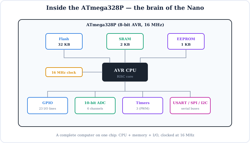
- Flash (32 KB) — stores your program; on the Nano ~2 KB is used by the bootloader.
- SRAM (2 KB) — working memory for variables while the program runs.
- EEPROM (1 KB) — small non-volatile store that survives power-off.
- Peripherals — 10-bit ADC, three timers (for PWM & timing), and hardware UART, SPI and I2C.
Full Arduino Nano Pinout
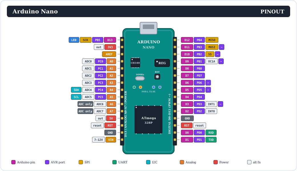
Here is the complete pinout — all 30 pins in two rows of 15. Every pin carries an Arduino number, its AVR port name (PBx / PCx / PDx) and any alternate function — ADC, PWM (~), SPI, I2C or UART.
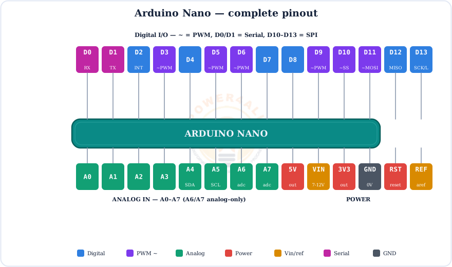
Prefer a simpler view? This colour-coded map groups the pins by what they do:
Every Pin Explained
Let's go through each group of pins and exactly what it does.
Digital pins (D0–D13)
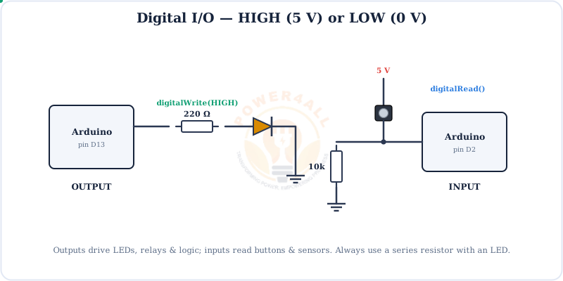
14 general-purpose pins that read or write two states only — HIGH (5 V) or LOW (0 V). Set direction with pinMode(), then use digitalWrite() or digitalRead(). Each pin handles ~20 mA (40 mA absolute max). Several have special roles:
D0 (RX) & D1 (TX)
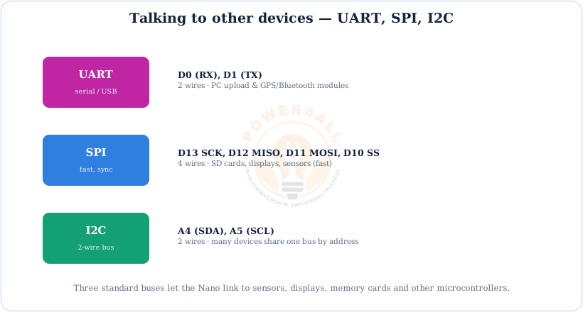
Hardware serial/UART. Shared with mini-USB upload & the Serial Monitor — avoid using them as I/O while using Serial.
D2 & D3
External interrupts (INT0, INT1) — respond instantly to a signal with attachInterrupt().
D3, 5, 6, 9, 10, 11
PWM (~) outputs — analogWrite(0–255) for dimming, speed & tone.
D10–D13
SPI bus — 10 = SS, 11 = MOSI, 12 = MISO, 13 = SCK.
D13
Wired to the on-board “L” LED — perfect for a first test with no extra parts.
Analog input pins (A0–A7)
The Nano has eight analog inputs (two more than the Uno), each connected to a 10-bit ADC that converts 0–5 V into a number from 0 to 1023 using analogRead(). A few points:
- A0–A5 can also be used as digital pins; A6 & A7 are analog-only (they have no digital or port function).
- A4 = SDA and A5 = SCL — the hardware I2C bus.
- AREF lets you supply an external analog reference voltage for the ADC.
Power pins
| Pin | What it does |
|---|---|
| VIN | Raw input — feed 7–12 V here to power the board. |
| 5V | Regulated 5 V output to power sensors and modules. |
| 3.3V | 3.3 V from the on-board regulator, ~50 mA. |
| GND | Ground (0 V) — there are two GND pins. |
| RESET (RST) | Pull LOW to restart the sketch (same as the reset button). |
| AREF | Optional external reference voltage for the ADC. |
Quick rule of thumb
A pin can be one thing at a time. If you use SPI, pins 10–13 are busy; if you use I2C, A4/A5 are busy; if you use Serial, D0/D1 are busy. Reach for A6/A7 when you just need extra analog reads.
Powering the Nano
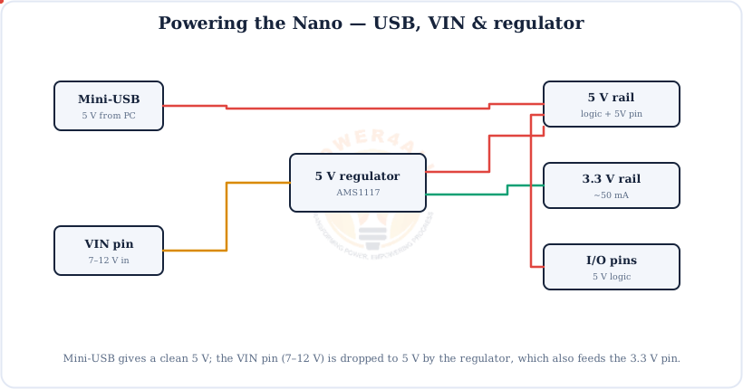
The Nano has no DC barrel jack. Power it over mini-USB (5 V), from 7–12 V on VIN through the on-board regulator, or with a regulated 5 V on the 5V pin.
Don't back-feed and overload
Power from one source at a time. The 5 V pin can supply a few hundred mA; 3.3 V only ~50 mA. Motors and LED strips need their own supply with a common ground — never run them straight off an I/O pin.
Digital I/O
Digital pins are the simplest: output a HIGH/LOW to drive an LED or relay, or read a HIGH/LOW input from a button or sensor.
// digital output + input
void setup() {
  pinMode(13, OUTPUT);      // LED pin
  pinMode(2, INPUT);        // button pin
}
void loop() {
  int pressed = digitalRead(2);      // HIGH or LOW
  digitalWrite(13, pressed);         // LED follows the button
}
PWM Output (~)
The Nano can't output a true analog voltage, but it can fake one with PWM — switching a pin on and off fast. The fraction of time it stays ON (the duty cycle) sets the average level.
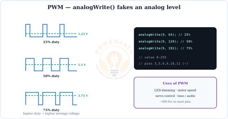
analogWrite(pin, 0–255) on the six ~ pins (3, 5, 6, 9, 10, 11).// fade an LED on a PWM pin (~9) void setup() { pinMode(9, OUTPUT); } void loop() { for (int v = 0; v <= 255; v++) { analogWrite(9, v); delay(5); } for (int v = 255; v >= 0; v--) { analogWrite(9, v); delay(5); } }
Analog Input (ADC)
The eight analog pins measure a continuous voltage. The 10-bit ADC turns 0–5 V into a number from 0 to 1023 — ideal for potentiometers, light sensors and temperature sensors.
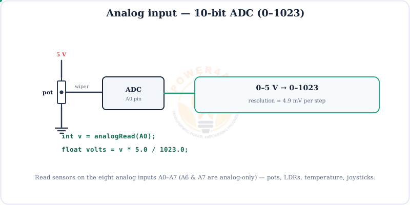
v * 5.0 / 1023.0.// read a sensor and print volts void setup() { Serial.begin(9600); } void loop() { int raw = analogRead(A0); // 0..1023 (try A6/A7 too) float volts = raw * 5.0 / 1023.0; Serial.println(volts); delay(200); }
Communication: UART, SPI & I2C
Three standard buses let the Nano talk to other chips — sensors, displays, memory cards and even other Arduinos.
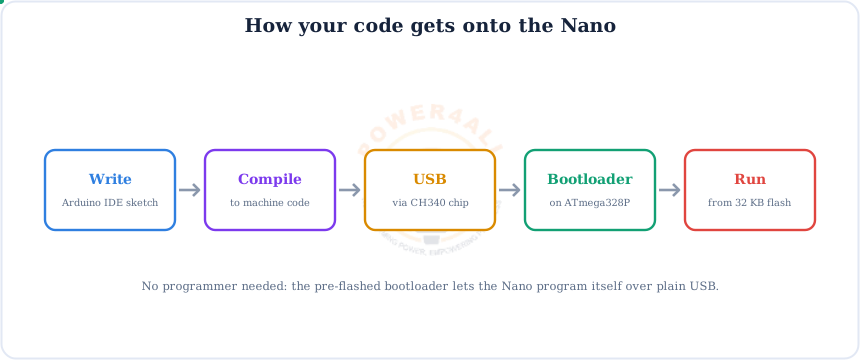
How Code Gets onto the Nano
You write a sketch in the Arduino IDE, and one mini-USB cable does the rest. A CH340 (or FT232) chip turns USB into serial.
CH340 driver
Many low-cost Nano clones use the CH340 USB-serial chip. If the board doesn't show up as a port, install the free CH340 driver, then pick the port under Tools → Port.
Every sketch has two functions: setup() runs once at power-up, and loop() repeats forever.
void setup() {
  // runs once — set up pins, start Serial, etc.
}
void loop() {
  // runs over and over — your main program
}
Arduino Nano vs Uno
Same brain, same code — so which do you pick? The Nano is smaller and breadboard-ready with two extra analog pins; the Uno is bigger, takes shields and has a DC jack.
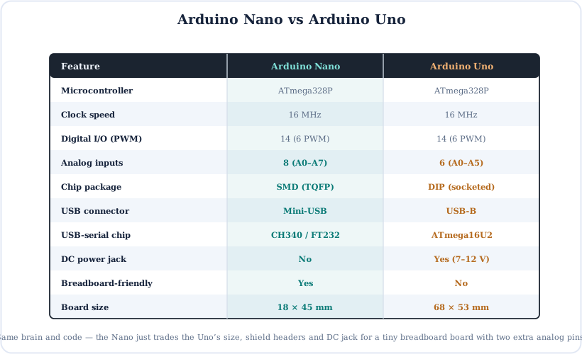
Choose the Nano for compact, breadboard and permanent builds where space matters. Choose the Uno for learning with shields, easy chip swaps and a barrel-jack supply.
Code Examples
A few short, copy-paste sketches — they run identically on the Nano and the Uno.
1. Blink the on-board LED
void setup() {
  pinMode(LED_BUILTIN, OUTPUT);       // pin 13
}
void loop() {
  digitalWrite(LED_BUILTIN, HIGH);
  delay(1000);
  digitalWrite(LED_BUILTIN, LOW);
  delay(1000);
}
2. Print to the Serial Monitor
void setup() {
  Serial.begin(9600);
  Serial.println("Hello from the Nano!");
}
void loop() {
  Serial.println(millis());           // ms since power-up
  delay(1000);
}
3. Read a button (internal pull-up)
void setup() {
  pinMode(2, INPUT_PULLUP);           // no external resistor needed
  pinMode(13, OUTPUT);
}
void loop() {
  // pressed = LOW with a pull-up
  if (digitalRead(2) == LOW) digitalWrite(13, HIGH);
  else                        digitalWrite(13, LOW);
}
Beginner Mini-Projects
Because the Nano plugs straight into a breadboard, these are especially quick to wire. The code is complete — upload and go.
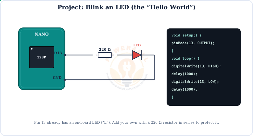
Project 1 — Blink an LED
void setup() { pinMode(13, OUTPUT); }
void loop() {
  digitalWrite(13, HIGH); delay(500);
  digitalWrite(13, LOW);  delay(500);
}
Project 2 — Push-button controlled LED
void setup() {
  pinMode(2, INPUT_PULLUP);
  pinMode(13, OUTPUT);
}
void loop() {
  if (digitalRead(2) == LOW)   // button pressed
    digitalWrite(13, HIGH);
  else
    digitalWrite(13, LOW);
}
Project 3 — Potentiometer LED dimmer
void setup() { pinMode(9, OUTPUT); }
void loop() {
  int raw = analogRead(A0);              // 0..1023
  int level = map(raw, 0, 1023, 0, 255); // scale to PWM
  analogWrite(9, level);                  // brightness follows the knob
}
Project 4 — Two-sensor read (using A6 & A7)
void setup() { Serial.begin(9600); }
void loop() {
  int a = analogRead(A6);      // analog-only pin
  int b = analogRead(A7);      // analog-only pin
  Serial.print(a); Serial.print(","); Serial.println(b);
  delay(200);
}
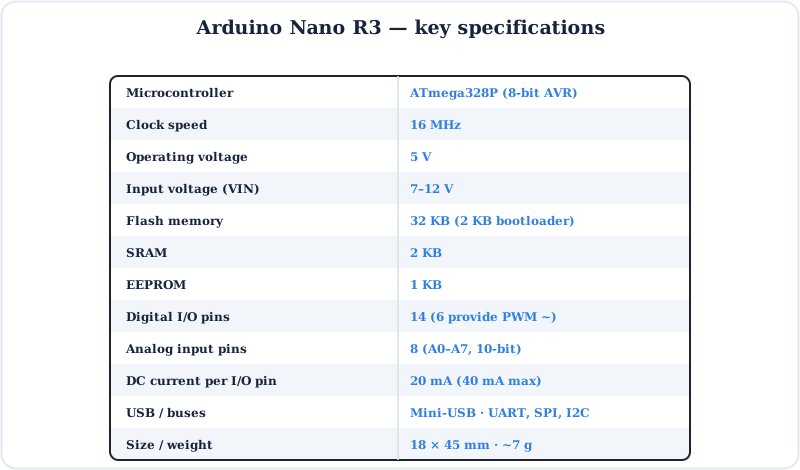
Specifications
The Arduino Nano at a glance.
Key Terms — Glossary
| Term | Meaning |
|---|---|
| Microcontroller | A single chip with CPU, memory and I/O — here, the ATmega328P. |
| Sketch | An Arduino program, with setup() and loop(). |
| SMD / TQFP | Surface-mount chip package — the Nano's ATmega328P is soldered flat, not socketed. |
| PWM (~) | Pulse-width modulation; fakes an analog level via duty cycle. |
| ADC | Analog-to-digital converter; 10-bit (0–1023) on the Nano. |
| A6 / A7 | Analog-only inputs (no digital function) — unique to the Nano/Mini. |
| CH340 / FT232 | USB-serial chip that bridges mini-USB to the MCU's UART. |
| Bootloader | Small program that lets the Nano flash itself over USB. |
| VIN | Raw voltage input (7–12 V) to power the board. |
Frequently Asked Questions
Quick answers to the questions people ask most about the Arduino Nano.
What is the Arduino Nano?
A small, breadboard-friendly microcontroller board built around the 8-bit ATmega328P at 16 MHz, with 14 digital pins, 8 analog inputs, 32 KB flash and 5 V logic. It runs the same code as the Uno in a much smaller form factor and is programmed over mini-USB.
What is the difference between the Nano and Uno?
Same ATmega328P, 16 MHz and 14 digital pins (6 PWM). The Nano is far smaller and breadboard-friendly, has 8 analog inputs vs 6, uses mini-USB with a CH340/FT232 chip, has no DC barrel jack, and uses an SMD chip instead of the Uno's socketed DIP.
How many pins does the Nano have?
30 pins in two rows of 15: 14 digital I/O (0–13, PWM on 3, 5, 6, 9, 10, 11), 8 analog inputs (A0–A7), and power pins 5V, 3.3V, VIN, GND, RESET and AREF.
How many analog pins does the Nano have?
Eight (A0–A7), all 10-bit. That's two more than the Uno. A6 and A7 are analog-only and can't be used as digital pins; A4/A5 also carry the I2C SDA/SCL lines.
How do I power the Nano?
From mini-USB (5 V), from 7–12 V on the VIN pin through the regulator, or with a regulated 5 V on the 5V pin. There is no barrel jack. Use one source at a time; each I/O pin handles ~20 mA.
How do I program the Nano (CH340 driver)?
Write a sketch in the Arduino IDE, connect over mini-USB, pick the board and port, and click Upload. Many clones use the CH340 chip — if no port appears, install the free CH340 driver first.
Does the Nano support SPI and I2C?
Yes. SPI is on pins 13 (SCK), 12 (MISO), 11 (MOSI), 10 (SS); I2C is on A4 (SDA) and A5 (SCL); and the UART is on D0/D1, shared with USB.
Can I use A6 and A7 as digital pins?
No. A6 and A7 are analog-input-only on the ATmega328P's TQFP package — use them with analogRead(). For digital I/O use pins 0–13 or A0–A5.
Conclusion & Key Takeaways
The Arduino Nano is the Uno's pocket-sized twin: the same capable ATmega328P and code, on a board that lives on a breadboard.
ATmega328P
16 MHz, 32 KB flash.
14 + 8 pins
Digital + analog.
A6 / A7
Two extra analog-only.
Mini-USB
CH340 / FT232.
Breadboard
Tiny 18×45 mm.
Uno-compatible
Same sketches run.