ESP32
The chip that put Wi-Fi and Bluetooth into every maker project. The ESP32 packs a dual-core 240 MHz CPU, Wi-Fi + Bluetooth, touch, ADC, DAC and PWM into one low-cost chip. This guide covers the DevKitC board and WROOM-32 module, a complete 38-pin pinout with every GPIO explained, which pins are safe, power and deep sleep, and finishes with code examples and beginner projects.
Complete Learning Path — ESP32
From the board, module and chip, to a full pinout with every GPIO, safe pins, power, analog, touch, PWM, buses, Wi-Fi, Bluetooth, deep sleep, uploading, code and projects
What is the ESP32?
The ESP32 is a low-cost Wi-Fi + Bluetooth microcontroller from Espressif Systems. It has a dual-core 32-bit processor at up to 240 MHz, 520 KB of RAM and a big set of peripherals. That makes it the go-to chip for IoT: smart switches, sensor loggers, web dashboards and BLE gadgets.
You rarely use the bare chip. Most people buy a development board such as the ESP32 DevKitC (38 pins) or the popular DevKit V1 (30 pins). The board carries the ESP32-WROOM-32 module plus everything needed to power and program it over one USB cable.
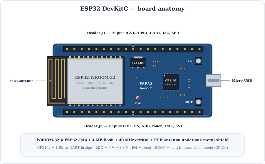
Parts of the DevKitC board
ESP32-WROOM-32
The shielded module: ESP32 chip, 4 MB flash, a 40 MHz crystal and the PCB antenna.
CP2102 / CH340
USB-to-UART bridge. It turns USB into serial for uploading code and for the Serial Monitor.
3.3 V LDO
Drops the 5 V from USB down to the 3.3 V the ESP32 needs (for example AMS1117-3.3).
EN button
Pulls the EN (enable) pin LOW to reset the chip. It restarts your sketch.
BOOT button
Holds GPIO0 LOW at reset to enter the ROM bootloader (flash mode). You can also read it as a button in your sketch.
The ESP32-WROOM-32 Module
The metal can on the board is the ESP32-WROOM-32, an 18 × 25.5 mm module. It holds the ESP32 chip together with the parts it needs to run. The module is radio-certified, so board makers can solder it down without doing any RF design.
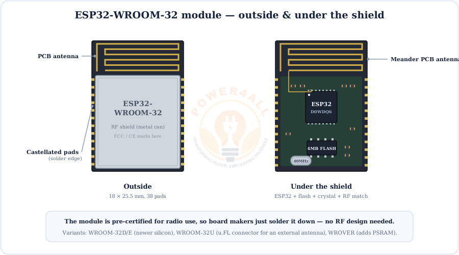
- WROOM-32 / 32D / 32E: PCB antenna. The D and E versions use newer chip revisions (E fixes early silicon bugs).
- WROOM-32U / 32UE: a u.FL connector instead of the PCB antenna, for an external antenna and longer range.
- WROVER: adds 4–8 MB PSRAM for cameras and large buffers. GPIO16/17 are then used by the PSRAM.
Keep the antenna clear
The PCB antenna at the end of the module needs free space. Don't place metal, batteries or a ground plane under or right next to it, or Wi-Fi range drops sharply.
Inside the ESP32 Chip
The ESP32 is a full system-on-chip (SoC). It has two Xtensa LX6 cores, an ultra-low-power (ULP) co-processor, on-chip memory, a 2.4 GHz radio and dozens of peripherals.
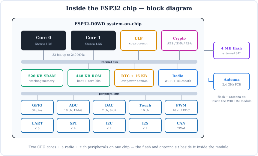
- Two cores: with the Arduino core, Wi-Fi and Bluetooth run on core 0 and your
loop()runs on core 1. FreeRTOS lets you add tasks on either core. - ULP co-processor: a tiny CPU that can read sensors while the main cores sleep, which is key for battery life.
- Memory: 520 KB SRAM for variables, 448 KB ROM for boot code, 16 KB RTC RAM that survives deep sleep, and 4 MB external flash for your program.
- Crypto hardware: AES, SHA, RSA and a true random-number generator for secure TLS connections.
Full ESP32 DevKitC Pinout
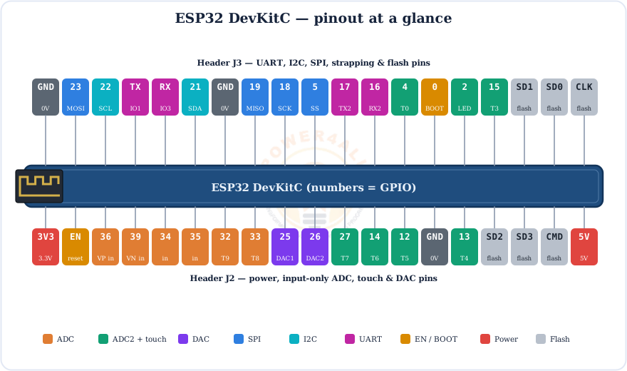
Here is the complete 38-pin ESP32 DevKitC pinout. Every header pin shows its GPIO number, its ADC channel, touch channel and alternate functions: DAC, SPI, I2C, UART, strapping and flash.
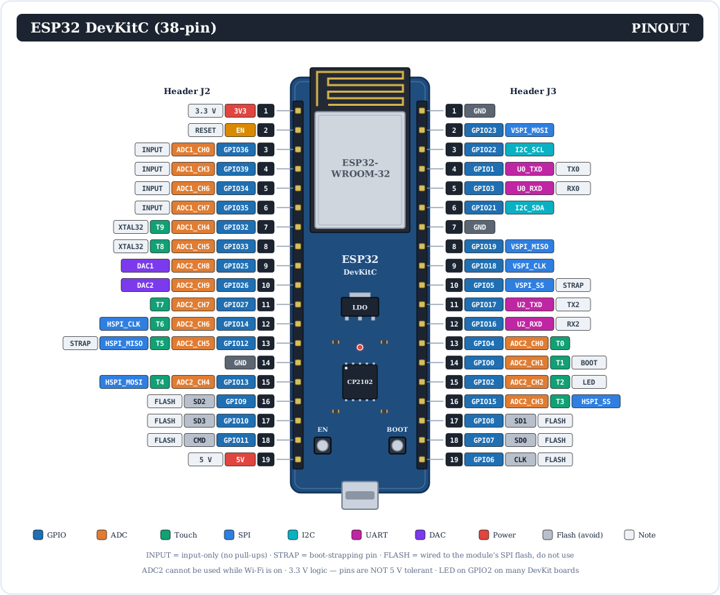
Want a quicker map? This colour-coded overview shows both headers with the GPIO numbers as printed on most boards:
30-pin DevKit V1 boards
The common 30-pin DOIT ESP32 DevKit V1 uses the same GPIO numbers but leaves out the six flash pins (GPIO6–11), GPIO0 and one GND, and calls the 5 V pin VIN. Its pins are printed as D23, D22…, where D23 = GPIO23. Always check the silkscreen on your own board.
Every ESP32 Pin Explained
Now let's go through each group of pins and what it does. In Arduino code you use the GPIO number directly, for example pinMode(23, OUTPUT).
Power & control pins
| Pin | What it does |
|---|---|
| 5V (VIN) | Connected to USB 5 V. Feed a regulated 5 V here to power the board without USB (the on-board LDO makes 3.3 V). |
| 3V3 | The regulated 3.3 V rail. It powers small sensors, or takes a clean 3.3 V supply directly, bypassing the LDO. |
| GND | Ground (0 V). There are several; tie all grounds in your circuit together. |
| EN | Chip enable / reset. It is pulled HIGH; taking it LOW resets the ESP32 (same as the EN button). |
General-purpose GPIO
Any GPIO can be an input or an output with pinMode(), digitalWrite() and digitalRead(). They also have internal pull-up and pull-down resistors (INPUT_PULLUP, INPUT_PULLDOWN). Logic is 3.3 V. Keep each pin to about 12–20 mA (40 mA absolute max), and drive relays and motors through a MOSFET or transistor.
GPIO34, 35, 36, 39
Input only: no output and no internal pull-ups. They are ideal for analog sensors on ADC1. 36/39 are labelled VP/VN.
ADC1: GPIO32–39
Six analog inputs that keep working with Wi-Fi on. They are the first choice for sensors.
ADC2: 0, 2, 4, 12–15, 25–27
Analog inputs that stop working while Wi-Fi runs. They are fine as digital pins at any time.
GPIO25 & 26
The two 8-bit DAC outputs (DAC1, DAC2), giving a true analog voltage from 0 to 3.3 V.
Touch T0–T9
Capacitive touch on GPIO 4, 0, 2, 15, 13, 12, 14, 27, 33, 32.
GPIO32 & 33
Can also connect an external 32.768 kHz crystal for an accurate RTC in deep sleep.
Special pins to respect
- Strapping pins (GPIO0, 2, 5, 12, 15): read once at reset to choose the boot mode and flash voltage. GPIO0 LOW = download mode; GPIO12 HIGH at boot selects 1.8 V flash and stops a WROOM-32 from booting. Don't connect anything that forces these pins to the wrong level at power-up.
- GPIO1 (TX0) & GPIO3 (RX0): UART0, wired to the USB bridge for uploading and
Serial. Using them as I/O breaks the Serial Monitor. - GPIO6–11 (SD0–SD3, CMD, CLK): connected to the module's SPI flash. Never use them, or the chip crashes.
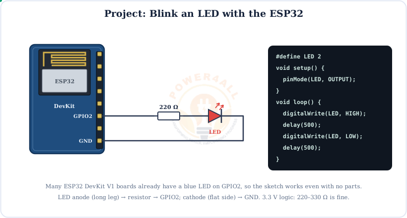
- GPIO2: drives the on-board blue LED on many DevKit V1 boards. It must be LOW or floating when you flash the chip.
Which ESP32 Pins Are Safe to Use?
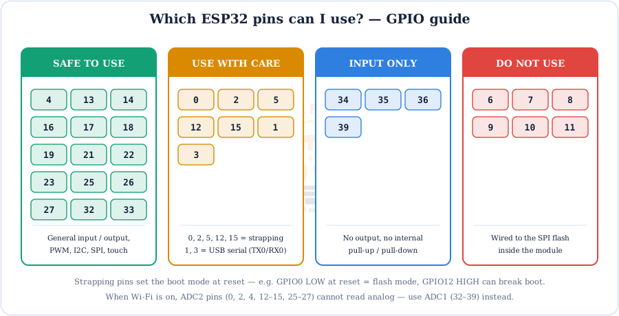
The question every beginner asks. Here are all the DevKit GPIOs sorted into four groups:
Handy default picks
LEDs and outputs: GPIO 4, 16, 17, 18, 19, 23. Analog sensors with Wi-Fi: GPIO 32, 33, 34, 35. I2C: 21/22. Buttons: any safe pin with INPUT_PULLUP.
Powering the ESP32
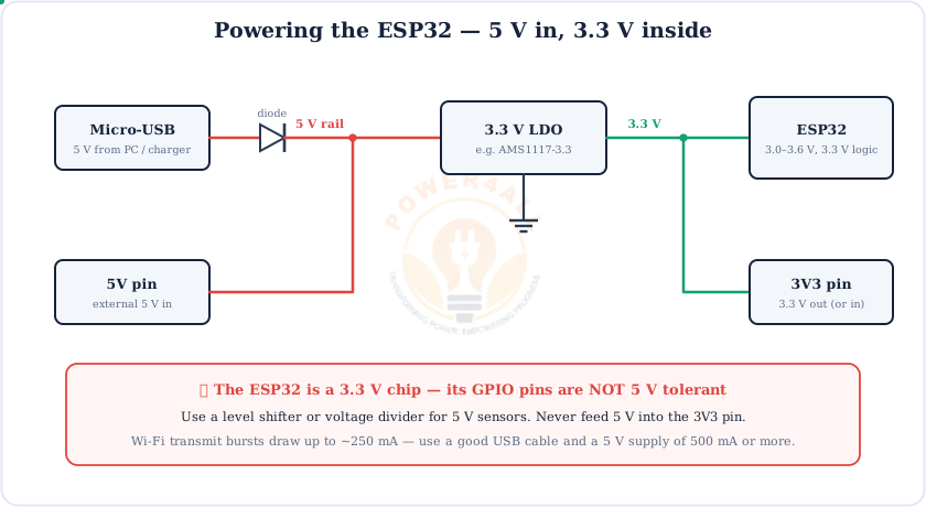
The ESP32 chip runs on 3.3 V. The DevKit board takes 5 V from USB or its 5V pin and uses an on-board LDO voltage regulator to make the 3.3 V.
Not 5 V tolerant
Putting 5 V on a GPIO can damage the ESP32. With 5 V modules (many HC-SR04 sensors, 5 V relays and LCDs), use a logic-level shifter or a resistor voltage divider (for example 1k/2k) on signals going into the ESP32.
Wi-Fi transmit bursts draw up to ~250 mA. Brown-outs and random resets usually mean a weak USB cable or supply, so add a 10–100 µF capacitor across 3V3–GND if you power it from a battery or a long cable.
PWM on the ESP32 (LEDC)
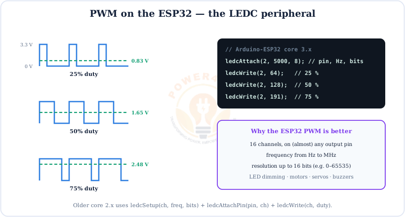
The ESP32 has a dedicated LEDC peripheral: 16 PWM channels with adjustable frequency and resolution, which can drive any output-capable GPIO. The duty cycle sets the average voltage (see pulse & PWM signals).
// fade an LED on GPIO2 (Arduino-ESP32 core 3.x)
void setup() {
  ledcAttach(2, 5000, 8);      // pin, 5 kHz, 8-bit (0..255)
}
void loop() {
  for (int d = 0; d <= 255; d++) { ledcWrite(2, d); delay(4); }
  for (int d = 255; d >= 0; d--) { ledcWrite(2, d); delay(4); }
}
On the older core 2.x use ledcSetup(0, 5000, 8); ledcAttachPin(2, 0); ledcWrite(0, duty); (channel-based). analogWrite() also works on core 2.0.14+ and 3.x.
Analog In & Out: ADC and DAC
The ESP32 has a 12-bit ADC (18 channels) that reads 0–3.3 V as 0 to 4095, and two 8-bit DACs that output a real analog voltage.
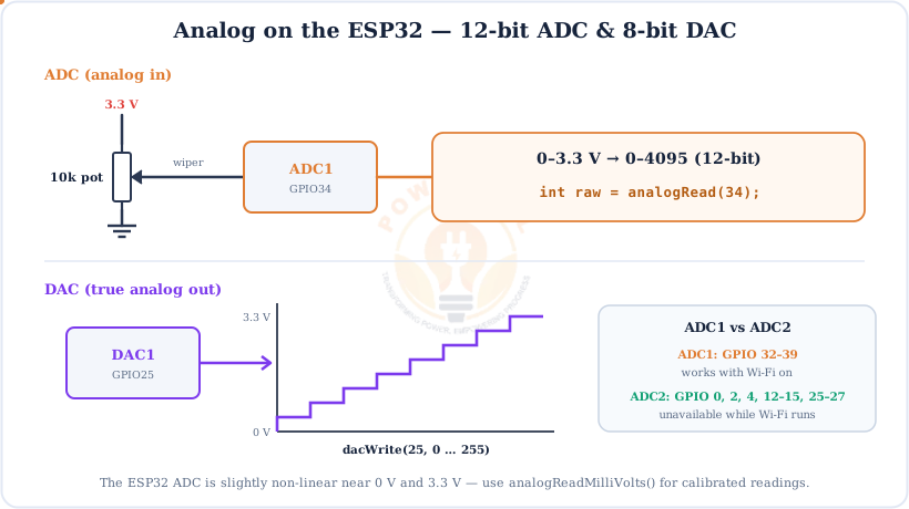
dacWrite(25, 0…255) → 0–3.3 V. Use ADC1 pins when Wi-Fi is on.// read a potentiometer on GPIO34 (ADC1) void setup() { Serial.begin(115200); } void loop() { int raw = analogRead(34); // 0..4095 int mv = analogReadMilliVolts(34); // calibrated millivolts Serial.printf("raw=%d mV=%d\n", raw, mv); delay(200); }
ESP32 ADC quirks
The raw ADC is non-linear near 0 V and above ~3.1 V, and a little noisy. Use analogReadMilliVolts() for calibrated values, average several samples, and keep inputs in the 0.15–3.1 V range for best accuracy. For precision work, use an external ADC such as the ADS1115 over I2C.
Capacitive Touch Sensing
Ten ESP32 pins can sense touch with no extra parts. A finger adds a little capacitance to a pad or wire, and the reading from touchRead() drops.
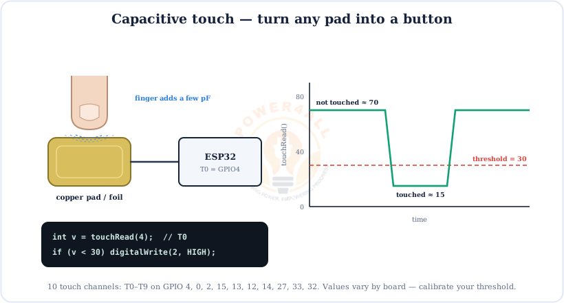
Touch pads work through thin plastic or glass, which is great for sealed buttons, and a touch can even wake the ESP32 from deep sleep (touchSleepWakeUpEnable()). Readings depend on wire length and board, so print them first and pick your own threshold.
Communication: UART, I2C & SPI
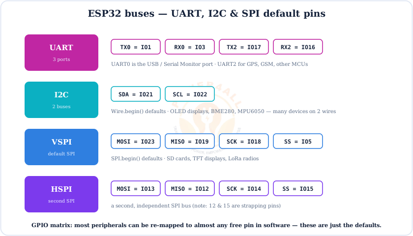
The ESP32 has 3 UARTs, 2 I2C buses and 4 SPI controllers (two free for you: VSPI and HSPI). Thanks to the GPIO matrix, most of them can be moved to almost any pin. These are the defaults the libraries use:
// use a second serial port and custom I2C pins
#include <Wire.h>
void setup() {
  Serial.begin(115200);                      // USB (UART0)
  Serial2.begin(9600, SERIAL_8N1, 16, 17);   // UART2: RX=16, TX=17
  Wire.begin(21, 22);                        // SDA, SCL (any pins work)
}
void loop() {
  if (Serial2.available()) Serial.write(Serial2.read());  // e.g. GPS bridge
}
Wi-Fi & Bluetooth
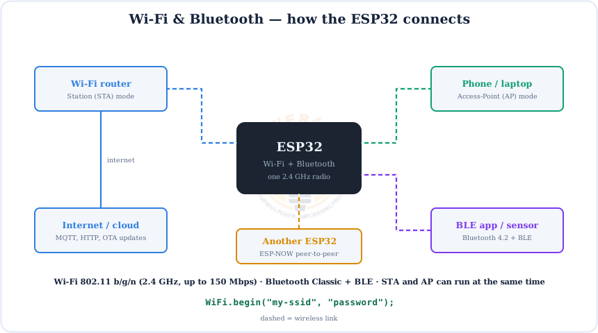
Wireless is the ESP32's superpower. One 2.4 GHz radio handles Wi-Fi 802.11 b/g/n, Bluetooth Classic and Bluetooth Low Energy (BLE).
Station (STA)
Connects to your Wi-Fi router for internet: web servers, MQTT, HTTP APIs, OTA updates.
Access Point (AP)
The ESP32 creates its own network. Phones connect straight to it, for example for Wi-Fi setup pages. It can run alongside STA.
Bluetooth / BLE
BLE for low-power phone apps and beacons; Classic for serial links (BluetoothSerial) and audio (A2DP).
ESP-NOW
Fast, router-free, low-power packets between ESP32 boards, which suits remotes and sensor networks.
// connect to Wi-Fi and print the IP address
#include <WiFi.h>
void setup() {
  Serial.begin(115200);
  WiFi.begin("YOUR_SSID", "YOUR_PASSWORD");
  while (WiFi.status() != WL_CONNECTED) { delay(500); Serial.print("."); }
  Serial.println(WiFi.localIP());          // e.g. 192.168.1.42
}
void loop() {}
Power Modes & Deep Sleep
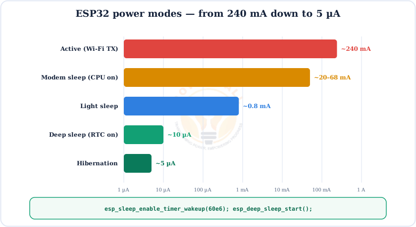
An ESP32 with Wi-Fi on can draw ~240 mA, but in deep sleep the chip needs only ~10 µA. Waking up, doing a job and sleeping again is how ESP32 sensors run for months on a battery.
| Wake-up source | How |
|---|---|
| Timer | esp_sleep_enable_timer_wakeup(us): wake every N microseconds. |
| External pin | esp_sleep_enable_ext0_wakeup(GPIO_NUM_33, 1): a button or sensor on an RTC GPIO. |
| Touch | touchSleepWakeUpEnable(T0, threshold): wake on a touch pad. |
| ULP program | The co-processor checks a sensor and wakes the main CPU only when needed. |
Board vs chip current
A DevKit board's LDO, USB chip and power LED add several mA, so a "deep-sleeping" DevKit may draw 5–15 mA. For true micro-amp sleep, use a bare module or a board designed for low power.
Programming the ESP32 & Uploading Code
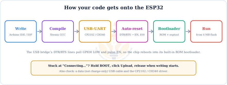
You can program the ESP32 in the Arduino IDE, Espressif's ESP-IDF, PlatformIO or MicroPython. For beginners, the Arduino IDE is the easiest start.
Set up the Arduino IDE
- Open File → Preferences and add this to Additional boards manager URLs:
https://espressif.github.io/arduino-esp32/package_esp32_index.json - Open Boards Manager, search esp32 and install esp32 by Espressif Systems.
- Select Tools → Board → ESP32 Dev Module and your board's Port. No port? Install the CP210x or CH340 USB driver.
- Click Upload. Open the Serial Monitor at 115200 baud, the ESP32 default.
“Failed to connect… Connecting…”
Hold the BOOT button when you see Connecting… and release it once writing starts. If it still fails, try another (data) cable and check that nothing on GPIO0, 2 or 12 is forcing a bad level at reset.
ESP32 Code Examples
Short, copy-paste sketches for the Arduino IDE that cover the ESP32 essentials.
1. Blink an LED
#define LED 2
void setup() {
  pinMode(LED, OUTPUT);
}
void loop() {
  digitalWrite(LED, HIGH);
  delay(500);
  digitalWrite(LED, LOW);
  delay(500);
}
2. Read a button with the internal pull-up
void setup() {
  pinMode(4, INPUT_PULLUP);           // button between GPIO4 and GND
  pinMode(2, OUTPUT);
}
void loop() {
  digitalWrite(2, digitalRead(4) == LOW);   // LED on while pressed
}
3. Touch pin as a button
void setup() { Serial.begin(115200); pinMode(2, OUTPUT); }
void loop() {
  int v = touchRead(4);              // T0 = GPIO4
  Serial.println(v);                   // check your own values first
  digitalWrite(2, v < 30);
  delay(50);
}
4. Deep sleep with a timer wake-up
RTC_DATA_ATTR int bootCount = 0;      // kept in RTC memory during sleep
void setup() {
  Serial.begin(115200);
  bootCount++;
  Serial.printf("Boot number %d\n", bootCount);
  esp_sleep_enable_timer_wakeup(60ULL * 1000000);   // 60 s
  esp_deep_sleep_start();              // setup() runs again on wake
}
void loop() {}
Beginner ESP32 Mini-Projects
Each project uses a handful of cheap parts and complete code. Upload it and it works.
Project 1 — Wi-Fi LED switch (web server)
#include <WiFi.h>
#include <WebServer.h>
WebServer server(80);
void setup() {
  pinMode(2, OUTPUT);
  Serial.begin(115200);
  WiFi.begin("YOUR_SSID", "YOUR_PASSWORD");
  while (WiFi.status() != WL_CONNECTED) delay(500);
  Serial.println(WiFi.localIP());
  server.on("/",    [](){ server.send(200, "text/html",
    "<h1>ESP32</h1><a href='/on'>ON</a> | <a href='/off'>OFF</a>"); });
  server.on("/on",  [](){ digitalWrite(2, HIGH); server.sendHeader("Location", "/"); server.send(303); });
  server.on("/off", [](){ digitalWrite(2, LOW);  server.sendHeader("Location", "/"); server.send(303); });
  server.begin();
}
void loop() { server.handleClient(); }
Project 2 — Touch lamp
bool on = false;
void setup() { pinMode(2, OUTPUT); }
void loop() {
  if (touchRead(4) < 30) {            // touched
    on = !on;
    digitalWrite(2, on);
    while (touchRead(4) < 30) delay(10);  // wait for release
  }
}
Project 3 — 12-bit potentiometer dimmer
void setup() {
  ledcAttach(2, 5000, 12);         // 12-bit PWM: 0..4095
}
void loop() {
  ledcWrite(2, analogRead(34));      // ADC 0..4095 -> duty 0..4095
  delay(10);
}
Project 4 — Battery sensor that sleeps
void setup() {
  Serial.begin(115200);
  int light = analogRead(35);         // 0..4095
  Serial.printf("Light level: %d\n", light);
  Serial.flush();
  esp_sleep_enable_timer_wakeup(5ULL * 60 * 1000000);  // 5 min
  esp_deep_sleep_start();
}
void loop() {}
ESP32 vs Arduino Uno
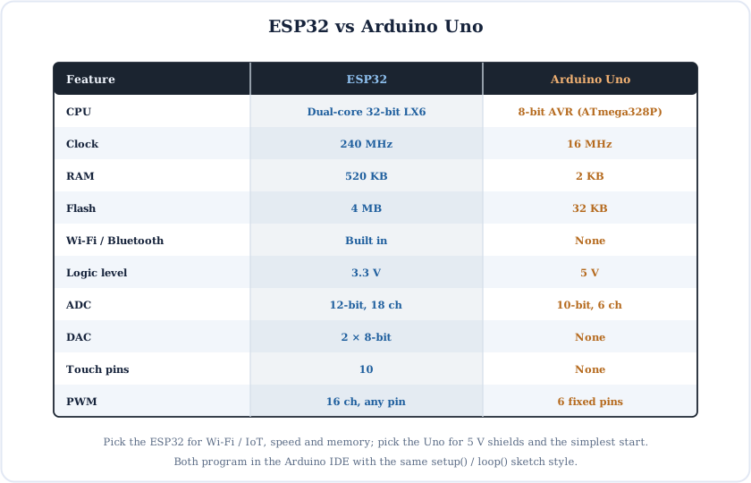
Both run Arduino sketches, but they are built for different jobs.
ESP32 vs ESP8266: the older ESP8266 has a single 80/160 MHz core, only one ADC input, no Bluetooth and fewer GPIOs. The ESP32 is the better pick for new projects at almost the same price.
ESP32 Specifications
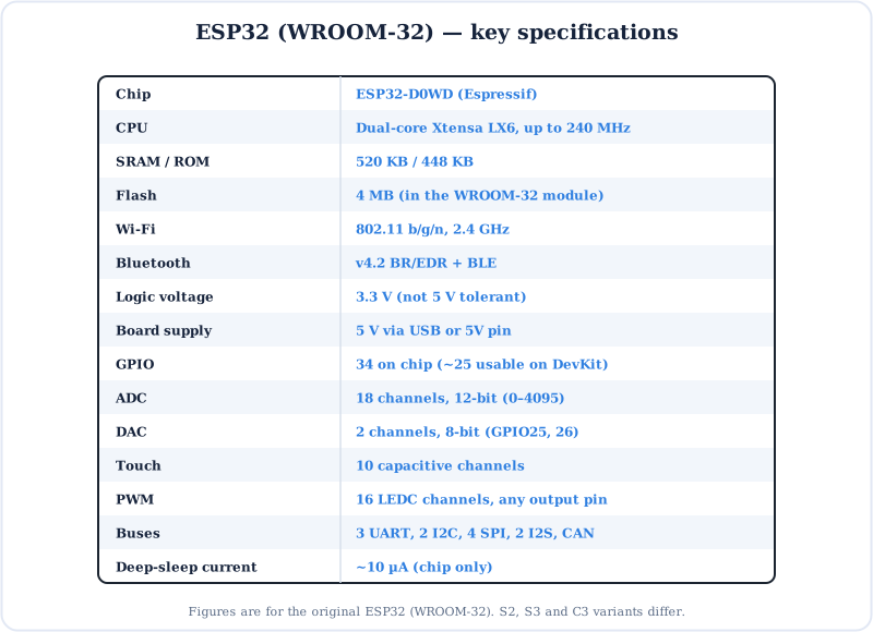
The ESP32 (WROOM-32) at a glance.
ESP32 family at a glance
| Chip | CPU | Wireless | Stand-out feature |
|---|---|---|---|
| ESP32 | 2 × Xtensa LX6, 240 MHz | Wi-Fi 4 + BT Classic + BLE 4.2 | DAC, touch, Hall sensor; the all-rounder |
| ESP32-S2 | 1 × Xtensa LX7, 240 MHz | Wi-Fi only | Native USB |
| ESP32-S3 | 2 × Xtensa LX7, 240 MHz | Wi-Fi + BLE 5 | Native USB, AI vector instructions |
| ESP32-C3 | 1 × RISC-V, 160 MHz | Wi-Fi + BLE 5 | Low cost, small |
| ESP32-C6 | 1 × RISC-V, 160 MHz | Wi-Fi 6 + BLE 5 + Zigbee/Thread | Matter smart-home ready |
Key Terms — Glossary
| Term | Meaning |
|---|---|
| SoC | System-on-chip: CPU, memory, radio and peripherals on one die. |
| WROOM-32 | Espressif's certified module: ESP32 + 4 MB flash + crystal + antenna under a shield. |
| DevKitC / DevKit V1 | USB development boards (38-pin / 30-pin) carrying the module. |
| GPIO | General-purpose input/output pin, 3.3 V logic on the ESP32. |
| Strapping pin | A pin sampled at reset to choose the boot mode (GPIO0, 2, 5, 12, 15). |
| ADC1 / ADC2 | The two 12-bit ADCs; ADC2 is unavailable while Wi-Fi is active. |
| DAC | Digital-to-analog converter, 8-bit, on GPIO25/26. |
| LEDC | The ESP32's PWM peripheral: 16 channels, any output pin. |
| GPIO matrix | Internal switch that routes peripherals (UART, I2C, SPI…) to almost any pin. |
| BLE | Bluetooth Low Energy: low-power wireless for phone apps and sensors. |
| ESP-NOW | Espressif's router-free, peer-to-peer wireless protocol. |
| Deep sleep | Mode where only the RTC and ULP stay on (~10 µA). |
| ULP | Ultra-low-power co-processor that runs during deep sleep. |
| esptool | The tool that talks to the ROM bootloader to write flash. |
Frequently Asked Questions
Quick answers to the questions people ask most about the ESP32.
What is the ESP32?
A low-cost microcontroller SoC from Espressif with a dual-core 32-bit Xtensa LX6 CPU at up to 240 MHz, 520 KB SRAM, built-in Wi-Fi 802.11 b/g/n and Bluetooth 4.2 with BLE. You can program it with the Arduino IDE, ESP-IDF or MicroPython, and it is one of the most popular chips for IoT.
How many GPIO pins does the ESP32 have?
The chip has 34 GPIOs. On a 38-pin DevKitC about 25 are practical: GPIO6–11 belong to the flash, GPIO34–39 are input-only, and GPIO0, 2, 5, 12 and 15 are strapping pins that need care.
Which ESP32 pins are safe to use?
GPIO 4, 13, 14, 16, 17, 18, 19, 21, 22, 23, 25, 26, 27, 32 and 33 are safe general-purpose pins on the WROOM-32. Use 34–39 only as inputs, treat 0, 2, 5, 12 and 15 with care, and never use 6–11.
Is the ESP32 5 V tolerant?
No. The ESP32 is a 3.3 V chip and its GPIOs are not 5 V tolerant. The board accepts 5 V on USB or the 5V pin and regulates it to 3.3 V, but signals from 5 V sensors need a level shifter or voltage divider.
Why doesn't analogRead work on some pins with Wi-Fi?
The ESP32 has two ADCs. The Wi-Fi driver uses ADC2 (GPIO0, 2, 4, 12–15, 25–27), so it can't be read while Wi-Fi is active. Use ADC1 pins GPIO32–39 for analog readings in Wi-Fi projects.
How do I fix the ESP32 “Connecting…” upload error?
Hold the BOOT button (GPIO0) when the IDE shows Connecting… and release it once writing starts. Also use a data-capable USB cable, install the CP2102/CH340 driver, pick the right port, and make sure nothing forces GPIO0, 2 or 12 to the wrong level at reset.
What is the difference between the ESP32 and the Arduino Uno?
The ESP32 has a dual-core 32-bit CPU at 240 MHz, 520 KB RAM, 4 MB flash and built-in Wi-Fi and Bluetooth, with 3.3 V logic. The Arduino Uno has an 8-bit 16 MHz ATmega328P, 2 KB RAM, 32 KB flash, no wireless and 5 V logic. Both program in the Arduino IDE.
How low can the ESP32 power consumption go?
The chip draws about 240 mA during Wi-Fi transmit, ~0.8 mA in light sleep, ~10 µA in deep sleep and ~5 µA in hibernation. A DevKit board draws more because of its regulator, USB bridge and LED, so battery projects often use a bare module.
Conclusion & Key Takeaways
The ESP32 gives you a fast dual-core processor, Wi-Fi and Bluetooth for the price of a basic microcontroller. Once you know which pins are safe and remember it's a 3.3 V chip, it is the best board for connected projects.
Dual-core 240 MHz
520 KB RAM, 4 MB flash.
Wi-Fi + Bluetooth
STA, AP, BLE, ESP-NOW.
3.3 V logic
Not 5 V tolerant.
Know your pins
Avoid 6–11; 34–39 input only.
ADC1 with Wi-Fi
ADC2 is busy when Wi-Fi is on.
Deep sleep
~10 µA for battery life.