Two-Port Networks
Model any circuit as a black box with an input and output port — four variables V1, I1, V2, I2 linked by two equations. The Z, Y, h and ABCD parameters are just different ways to write that relationship, and they power everything from transistor models to cascaded filters.
Complete Learning Path — Two-Port Networks
From the black-box idea and four variables, to the Z, Y, h and ABCD parameters, and interconnection
What Is a Two-Port Network?
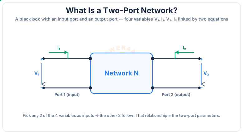
A two-port network is any circuit treated as a black box with two pairs of terminals — an input port and an output port. You do not care what is inside; you only care how the port voltages and currents relate.
Each port has a voltage and a current, giving four variables: V1, I1 at the input and V2, I2 at the output. Two equations link them, so if you know any two variables the other two follow. The coefficients in those equations are the two-port parameters — a compact fingerprint of the whole circuit.
Why it's powerful
A complicated amplifier or filter collapses to just four numbers. You can analyse, cascade and design with those numbers without ever re-solving the internal circuit.
The Four Variables & Sign Convention
Everything rests on a clear convention: both port currents are taken to flow into the network at the top terminal, and each port voltage is measured + at the top.
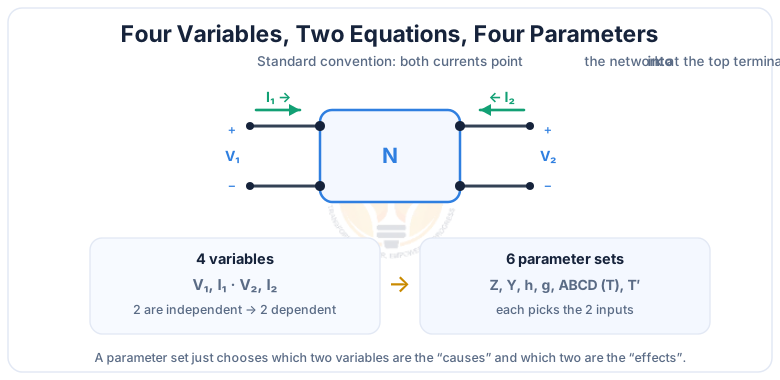
Two of the four variables are treated as independent (the causes) and two as dependent (the effects). Which two you pick decides the parameter set: currents as causes gives the Z parameters, voltages as causes gives the Y parameters, and mixed choices give the h and ABCD parameters.
Impedance (Z) Parameters
The Z parameters treat the currents as causes and give the voltages: they are open-circuit parameters, measured in ohms.
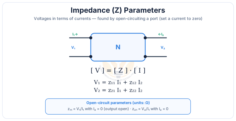
V1 = z11I1 + z12I2 · V2 = z21I1 + z22I2
open-circuit test: z11 = V1/I1 and z21 = V2/I1 with I2 = 0 (output open)
z11 and z22 are the driving-point (input/output) impedances; z12 and z21 are the transfer impedances. Z parameters are handy when two-ports are connected in series, because then the Z matrices simply add.
Admittance (Y) Parameters
The Y parameters are the mirror image: voltages are the causes and currents the effects. They are short-circuit parameters, measured in siemens.
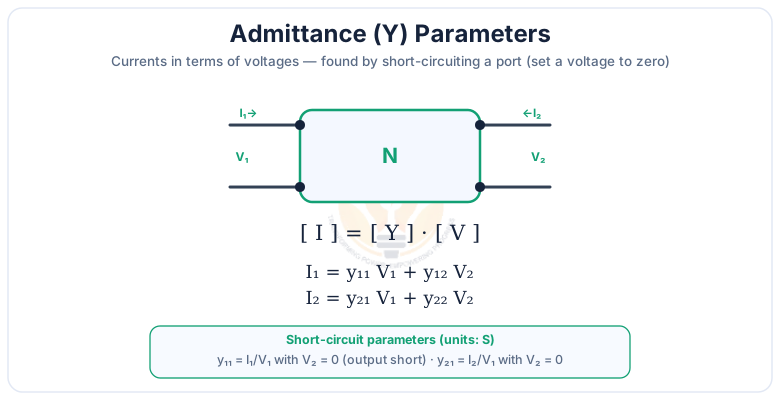
I1 = y11V1 + y12V2 · I2 = y21V1 + y22V2
short-circuit test: y11 = I1/V1 and y21 = I2/V1 with V2 = 0 (output short)
The Y matrix is the inverse of the Z matrix ([Y] = [Z]−1). Y parameters are the natural choice when two-ports are connected in parallel, because then the Y matrices add.
Hybrid (h) Parameters & the Transistor Model
The h parameters mix the two views — input current and output voltage are the causes — which is exactly what suits a transistor.
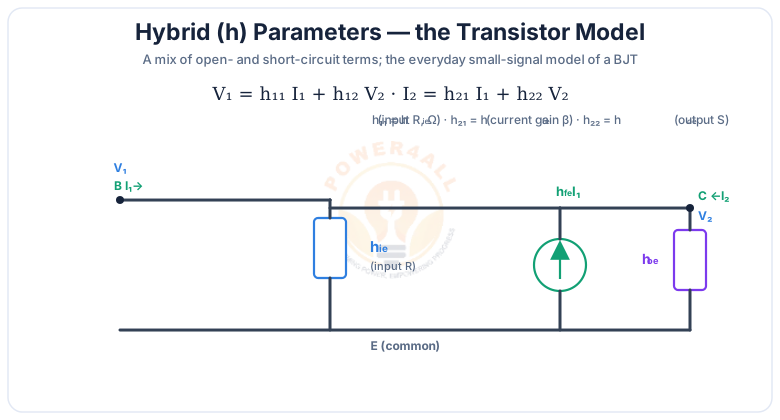
V1 = h11I1 + h12V2 · I2 = h21I1 + h22V2
h11 = hie (input R, Ω), h21 = hfe (current gain β), h12 = hre, h22 = hoe (output S)
Because the four h parameters have mixed units (an ohm, a siemens and two dimensionless ratios), they are called "hybrid". Datasheets quote a transistor's hfe (its current gain, β) and hie directly.
Transmission (ABCD) Parameters & Cascade
The ABCD (transmission or chain) parameters write the input in terms of the output — the one form that multiplies neatly when networks are chained.
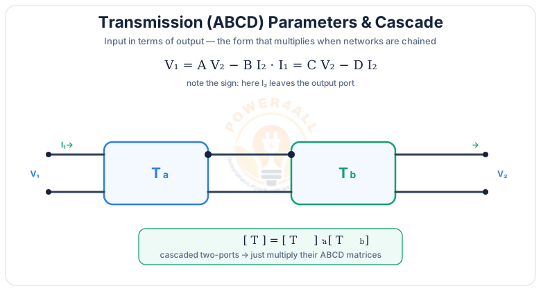
V1 = A·V2 − B·I2 · I1 = C·V2 − D·I2
I2 is taken as leaving the output port; for a reciprocal network AD − BC = 1
Here A is a voltage ratio, D a current ratio, B an impedance and C an admittance. Cascading is the killer feature: chain several stages and you just multiply their ABCD matrices in order — the reason they dominate transmission-line and filter analysis.
Choosing & Combining Parameter Sets
Every set describes the same network, so pick the one that makes your problem easiest — especially when interconnecting two-ports.
| Parameters | Cause → Effect | Units | Best for |
|---|---|---|---|
| Z (impedance) | I → V (open-circuit) | Ω | Two-ports in series (Z matrices add) |
| Y (admittance) | V → I (short-circuit) | S | Two-ports in parallel (Y matrices add) |
| h (hybrid) | I1, V2 → V1, I2 | mixed | Transistor amplifiers |
| ABCD (transmission) | output → input | mixed | Two-ports in cascade (matrices multiply) |
Reciprocity & symmetry
A network of only passive, bilateral parts is reciprocal: z12 = z21, y12 = y21, AD − BC = 1. If it also looks the same from either port it is symmetrical: z11 = z22 and A = D.
Applications
Two-port modelling is a workhorse of analog, RF and power engineering.
Cascaded stages
ABCD matrices multiply through multi-stage amplifiers and filter chains.
Transmission lines
Lines and cables are modelled as ABCD two-ports for power flow and matching.
Filter design
π and T (delta/wye) sections are two-ports combined by Z, Y or ABCD.
Transformers
A transformer is a classic two-port with simple ABCD parameters.
RF & microwave
S-parameters extend the two-port idea to high frequencies.
Key Terms at a Glance
The essential two-port vocabulary students and engineers search for.
Port
A terminal pair with equal in/out current.
Z parameters
Open-circuit impedances (Ω).
Y parameters
Short-circuit admittances (S).
h parameters
Hybrid, mixed units; transistor model.
ABCD
Transmission; multiply to cascade.
Reciprocal
z12 = z21, AD−BC = 1.
Frequently Asked Questions
Quick, clear answers to the questions people ask most about two-port networks.
What is a two-port network?
A circuit treated as a black box with two terminal pairs — an input port and an output port — described by four variables: V1, I1, V2, I2. Two equations relate them, and the coefficients are the network's parameters. Amplifiers, filters, lines and transformers are all modelled this way.
What are the Z (impedance) parameters?
They give the voltages from the currents: V1 = z11I1 + z12I2, V2 = z21I1 + z22I2. In ohms, they are open-circuit parameters — each found with a port open so one current is zero (e.g. z11 = V1/I1 with I2 = 0).
What are the Y (admittance) parameters?
They give the currents from the voltages: I1 = y11V1 + y12V2, I2 = y21V1 + y22V2. In siemens, they are short-circuit parameters (a port shorted so one voltage is zero). The Y matrix is the inverse of the Z matrix.
What are h parameters and why are they used for transistors?
The hybrid set: V1 = h11I1 + h12V2, I2 = h21I1 + h22V2, with mixed units. They map onto the BJT small-signal model: hie input resistance, hfe current gain (β), hoe output admittance — the values datasheets quote.
What are the ABCD (transmission) parameters?
They give input from output: V1 = A V2 − B I2, I1 = C V2 − D I2 (I2 leaving the output). Their advantage is cascading: chain two-ports and the overall ABCD matrix is the product of the individual matrices.
Why are there so many parameter sets?
Different problems make different variables convenient: Z and Y for series/parallel combinations, h for transistor amplifiers, ABCD for cascaded stages and lines. All describe the same network and convert to each other, so you use whichever gives the simplest algebra.
When are the Z parameters not defined?
When the required matrix can't be inverted. An ideal series impedance has no Y parameters, and an ideal shunt admittance has no Z parameters, because the open- or short-circuit measurement becomes infinite or indeterminate. Then you switch to a parameter set that is well defined for that network.
What is a reciprocal two-port network?
One built only from passive, bilateral elements (R, L, C) with no dependent sources. For a reciprocal network z12 = z21, y12 = y21, h12 = −h21 and AD − BC = 1. Transistor networks are generally not reciprocal.
What is a symmetrical two-port network?
One that looks the same from either port, so the ports can be swapped without changing its behaviour. Then z11 = z22, y11 = y22 and A = D. A symmetrical network is always reciprocal.
How do you combine two-port networks?
Match the parameter set to the connection: series → add the Z matrices, parallel → add the Y matrices, cascade → multiply the ABCD matrices. The right choice turns the combination into simple matrix addition or multiplication.
Conclusion & Key Takeaways
A two-port network reduces any circuit to four numbers relating its input and output — and the Z, Y, h and ABCD sets are just four ways to write them.
Black box, 2 ports
Four variables V1, I1, V2, I2.
Z: open-circuit
V from I, in Ω; add in series.
Y: short-circuit
I from V, in S; add in parallel.
h: hybrid
Transistor small-signal model.
ABCD: cascade
Multiply to chain stages.
Reciprocal / symmetric
z12=z21; z11=z22.