Gas Discharge Tube (GDT)
The surge arrester that stays invisible until a spike hits — then ionises its gas and crowbars the surge to earth. Learn how a gas discharge tube works, its construction, the sparkover voltage, glow & arc regions, the negative-resistance V–I curve, follow current, 2- vs 3-electrode types, GDT vs MOV vs TVS, and hybrid SPDs.
Complete Learning Path — Gas Discharge Tube
From what a GDT is and how it works, to its characteristic, circuit use, types, comparisons, ratings and applications
What Is a Gas Discharge Tube?
A gas discharge tube (GDT), also called a gas tube arrester or surge arrester, is a surge-protection component made of two (or three) metal electrodes sealed in a ceramic tube filled with inert gas at low pressure.
Under normal voltage the GDT does nothing — it is effectively an open circuit with an impedance of gigaohms and almost no leakage or capacitance. But when a surge pushes the voltage above the sparkover voltage, the gas ionises and the tube switches to a low-impedance arc that shorts the surge safely to ground. That "do nothing, then crowbar hard" behaviour is what makes a gas discharge tube one of the highest-energy surge protectors available.
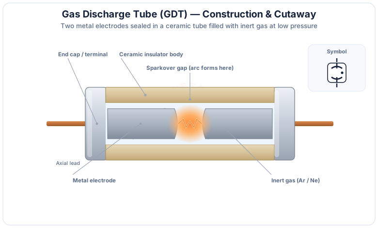
The one-line idea
Below sparkover it is an open switch; above sparkover it becomes almost a closed switch to ground. A GDT does not gently clamp — it crowbars.
How a Gas Discharge Tube Works
A GDT moves through four states as a surge arrives: high-impedance off, sparkover, glow discharge, and finally a low-impedance arc.
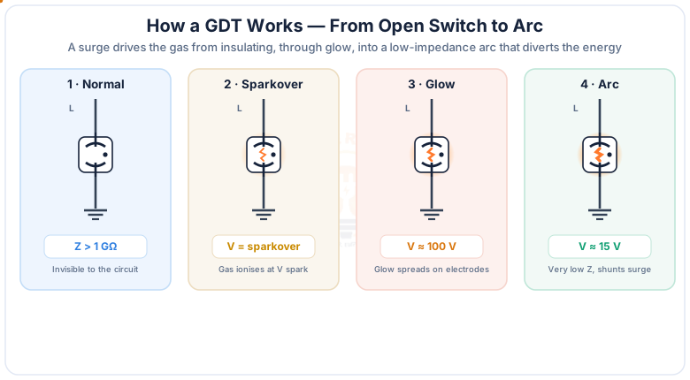
When the voltage reaches the sparkover voltage, the inert gas ionises and current begins to flow. The tube first enters a glow discharge at around 100 V, then, as current rises, transitions to an arc discharge at only about 15–30 V. In the arc state the GDT is nearly a short circuit, so it carries a huge surge current while holding only a low voltage across the line. Once the surge has passed and the current drops below the holding current, the arc extinguishes and the GDT snaps back to its high-impedance off state.
Fast surges overshoot
Because the gas needs a moment to ionise, a very fast surge can push the voltage above the DC sparkover before the tube fires — the impulse sparkover voltage. This overshoot is exactly why a fast clamp (MOV/TVS) is added downstream.
The V–I Characteristic (Negative Resistance)
The GDT's defining trait is its negative-resistance V–I curve: once it fires, the voltage falls as the current rises.
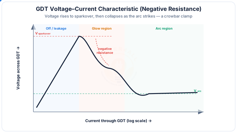
Unlike a varistor that clamps at a roughly fixed voltage, the GDT is a crowbar: after sparkover it collapses to a low arc voltage and effectively short-circuits the surge to ground. Because the voltage across it is so low during conduction, very little power is dissipated in the tube even at kiloamp surge currents — which is why GDTs survive far larger surges than clamping devices of the same size.
The GDT as a Surge Protector
In a protection circuit the GDT is wired line-to-ground (shunt), where it diverts the surge to earth and lets only a clamped let-through voltage reach the equipment.
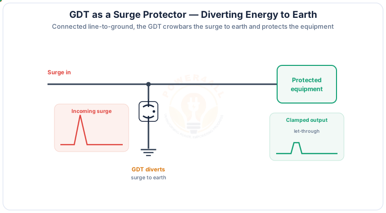
The GDT is normally the primary, high-energy stage of a surge protective device (SPD). It handles the bulk of a lightning or switching surge, while faster, lower-energy devices downstream trim the residual voltage. Good earthing and short leads matter: a long ground lead adds inductance and raises the effective let-through voltage.
Key Ratings of a GDT
A GDT datasheet is read through a handful of key parameters — get these right and the tube protects reliably.
Sparkover voltage
DC and impulse sparkover — where it fires. Set above the working voltage, below the equipment's withstand.
Surge current rating
Impulse (e.g. 8/20 µs) and AC discharge current the tube survives — often several kA to tens of kA.
Follow / holdover
Power-follow current and holdover voltage — will the arc clear after the surge on a live line?
Capacitance
Typically <1 pF — low enough for high-speed data and RF lines without distortion.
Insulation resistance
Gigaohms in the off state — negligible leakage across the tube.
Response time
Fast, but slower than a TVS — the gas takes time to ionise, hence the impulse overshoot.
Two-Electrode vs Three-Electrode GDT
GDTs come as a single spark gap for one line, or a three-electrode tube that protects a pair to a common ground.
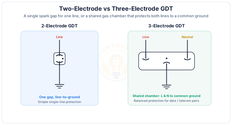
The three-electrode design is important for balanced lines. Because both gaps share one ionised gas volume, when one side sparks over it helps the other fire almost instantly, so the differential voltage between the two lines stays low — protecting sensitive line interfaces as well as diverting to ground.
Coordinated & Hybrid SPDs
A GDT rarely works alone. In a coordinated (hybrid) SPD it is teamed with an MOV and/or TVS so you get both high energy handling and a low let-through voltage.
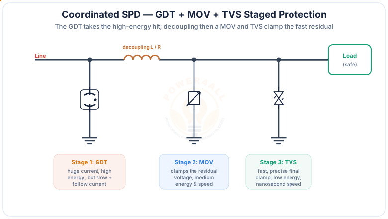
Stage 1 — GDT
Huge surge current to ground; high energy, but slower and can carry follow current.
Decoupling L / R
Series inductor or resistor develops the voltage that makes the GDT fire and separates stages.
Stage 2 — MOV
Clamps the residual voltage; medium energy and speed.
Stage 3 — TVS
Fast, precise final clamp with a low let-through voltage for sensitive electronics.
GDT vs MOV vs TVS Diode
The three main surge devices are complementary — a GDT crowbars, a varistor and TVS clamp.
| GDT | MOV (varistor) | TVS diode | |
|---|---|---|---|
| Action | Crowbar (arcs low) | Clamp | Clamp (fast) |
| Surge energy | Very high | Medium | Low |
| Speed | Slower (µs) | Fast (ns–µs) | Very fast (ps–ns) |
| Let-through V | Low arc V, but overshoots | Moderate clamp | Lowest, precise |
| Capacitance | Very low (<1 pF) | High | Low–moderate |
| Wear-out | Slow (arc erosion) | Degrades per surge | Very robust |
| Follow current | Possible on AC/DC | No | No |
In short: the GDT is the muscle (high energy), the TVS diode is the finesse (fast, precise), and the MOV sits between them — which is why serious protectors coordinate all three.
Applications of Gas Discharge Tubes
GDTs guard anything exposed to lightning or switching surges — especially lines and antennas where low capacitance matters.
Telecom & xDSL
Primary protection on phone and broadband pairs at the line entry.
Ethernet & data
3-electrode GDTs on data pairs; very low capacitance preserves signal integrity.
Coax, antenna & RF
CATV, base stations and antenna feeds where a low-C protector is essential.
AC mains SPDs
The high-energy first stage in mains surge protective devices.
Power & PV
Lightning and switching protection in supplies, inverters and solar strings.
Industrial & rail
Instrumentation, signalling and rugged equipment inputs.
Key Terms at a Glance
The essential gas-discharge-tube vocabulary engineers and students search for.
Gas discharge tube
Gas-filled spark-gap surge arrester.
Sparkover voltage
Voltage at which the gas ionises and fires.
Glow / arc
Conducting states (~100 V then ~15 V).
Crowbar
Collapses to low voltage, shorts surge.
Follow current
Power current that can sustain the arc.
Holdover voltage
Voltage below which the arc extinguishes.
Frequently Asked Questions
Quick, expert answers to the questions people ask most about gas discharge tubes.
What is a gas discharge tube (GDT)?
A gas discharge tube is a surge-protection component made of two or three metal electrodes with a small spark gap, sealed inside a ceramic or glass tube filled with an inert gas at low pressure. Normally it is an open circuit with a very high impedance, but when the voltage across it exceeds the sparkover voltage the gas ionises and the tube conducts a large surge current at a low arc voltage, diverting the surge safely to ground.
How does a gas discharge tube work?
When the voltage across a GDT rises above its sparkover voltage, the inert gas between the electrodes ionises. The tube passes quickly through a glow discharge, around 100 volts, and then strikes a low-impedance arc at only about 15 to 30 volts. In the arc state the GDT behaves almost like a closed switch, so it crowbars the surge current to ground while holding only a low voltage across the protected line. When the surge passes and the current falls below the holding current, the arc extinguishes and the tube returns to its high-impedance state.
What is the sparkover voltage of a GDT?
The sparkover voltage (or breakdown voltage) is the voltage at which the gas in the tube ionises and the GDT starts to conduct. There is a DC sparkover voltage measured with a slowly rising voltage and a higher impulse sparkover voltage measured with a fast surge, because a fast-rising surge reaches a higher voltage before the gas has time to ionise. Common GDTs have DC sparkover ratings from around 75 volts to several kilovolts.
What is follow current and holdover voltage in a GDT?
Follow current is the power-frequency current that can keep flowing through the GDT after the surge has passed, because the arc is still conducting and the normal system voltage sustains it. Holdover voltage is the maximum voltage at which the tube will reliably extinguish and stop conducting. On AC mains a GDT is chosen or coordinated so that follow current cannot latch it on; this is one reason GDTs are often combined with other devices.
Why does a gas discharge tube have a negative-resistance (crowbar) characteristic?
Once the gas ionises, more current makes the arc more conductive, so the voltage across the tube actually falls as the current rises. This falling voltage with rising current is a negative-resistance region, and it makes the GDT a crowbar device: instead of clamping at a set voltage like a varistor, it collapses to a very low arc voltage and short-circuits the surge to ground, which lets it handle very large surge currents with little heating.
What is the difference between a 2-electrode and a 3-electrode GDT?
A two-electrode GDT has a single spark gap and protects one line to ground. A three-electrode GDT has two gaps sharing one gas chamber, with line and neutral on the outer electrodes and a common ground in the centre. Because they share a chamber, when one gap sparks over the ionised gas helps the other fire almost immediately, giving balanced protection across line, neutral and ground, which is important for telecom and data pairs.
What is the difference between a GDT, a MOV and a TVS diode?
A GDT is a crowbar device that switches to a very low arc voltage and handles very high surge currents but responds relatively slowly and can carry follow current. A metal-oxide varistor (MOV) clamps the voltage at a set level, is faster than a GDT and handles medium energy, but degrades with repeated surges. A TVS diode clamps very fast and precisely with low let-through voltage but handles the least energy. They are complementary, so many surge protectors use them together.
Why are GDTs used together with MOVs or TVS diodes?
In a coordinated or hybrid surge protective device the GDT takes the high-energy hit and diverts most of the surge current to ground, a decoupling inductor or resistor separates the stages, and then a faster MOV or TVS clamps the residual voltage that gets through before and during the GDT firing. This combines the GDT's high current capability with the fast, precise clamping of the MOV and TVS, giving both high energy handling and a low let-through voltage.
What are the advantages and disadvantages of a gas discharge tube?
Advantages of a GDT are very high surge current capability, very low leakage and very low capacitance, high insulation resistance and a compact size. Disadvantages are a relatively slow response time, a sparkover voltage that overshoots on fast surges, the possibility of follow current on AC power lines, and a finite life after many high-energy strikes. These trade-offs are why GDTs are often used as the first stage alongside faster clamping devices.
What is the capacitance of a GDT and why does it matter?
A GDT has a very low capacitance, typically around 1 picofarad or less, because its electrodes are small and separated by gas. This very low capacitance is a major advantage on high-speed data and RF lines, where a higher-capacitance protector such as a large MOV or TVS would distort or attenuate the signal. It is a key reason GDTs are chosen for coaxial, antenna and high-frequency data protection.
Where are gas discharge tubes used?
Gas discharge tubes are used wherever high-energy surges from lightning or switching must be diverted: telephone and telecom line protection, xDSL and Ethernet data lines, coaxial and antenna feeds, CATV, base stations, AC mains surge protective devices, power supplies, measurement and instrumentation inputs, and railway and industrial equipment. They are usually the primary, high-energy stage of the protection.
Are gas discharge tubes polarity sensitive and can they be used on AC and DC?
A GDT is symmetrical and not polarity sensitive, so it works the same for either polarity and is suitable for both AC and DC circuits. On AC and DC power lines, however, follow current must be considered, because the sustained system voltage can keep the arc conducting after the surge; on such lines the GDT is chosen or coordinated with series impedance and other devices so that it clears reliably.
Conclusion & Key Takeaways
A gas discharge tube is the heavy-lifter of surge protection: invisible until a spike arrives, then it ionises and crowbars the energy to earth — best paired with faster clamps for a complete SPD.
Gas spark gap
Electrodes in inert gas.
Sparkover → arc
Off, glow, then low-V arc.
Crowbar
Shorts the surge to ground.
High energy, low C
kA surges, <1 pF.
Watch follow current
On AC/DC lines.
Pair with MOV/TVS
Coordinated hybrid SPD.