Common-Mode Choke
The two-winding inductor that blocks common-mode noise but passes the signal — the heart of every EMI filter. Learn how a common-mode choke (CMC) works, common-mode vs differential-mode noise, its impedance vs frequency, the dot convention, X- & Y-capacitors, how to choose one, and where it is used.
Complete Learning Path — Common-Mode Choke
From what a common-mode choke is and how it works, to the EMI filter, impedance, selection and applications
What Is a Common-Mode Choke?
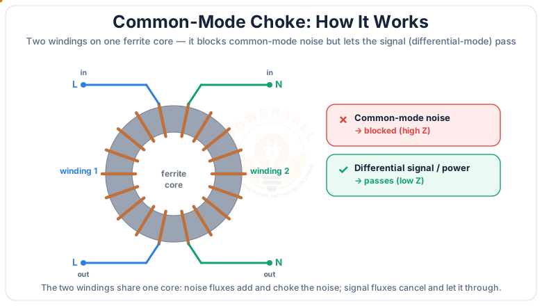
A common-mode choke (CMC), also called a common-mode filter or common-mode inductor, is a passive EMI-suppression component made of two windings on a single magnetic core. Wired in series with the two conductors of a circuit — line and neutral, or a differential data pair — it blocks common-mode noise while letting the wanted signal or power pass.
That selectivity is the whole point. A common-mode choke presents a high impedance to common-mode noise current (which flows the same way on both wires) but almost zero impedance to the differential-mode current that actually carries your signal or power. This is why the common-mode choke is the first component in nearly every EMI / EMC filter, from a phone charger to a solar inverter.
The one-line idea
Same current on both wires (noise) → blocked. Opposite currents on the two wires (your signal) → passes. One component, two completely different behaviours.
Common-Mode vs Differential-Mode Noise
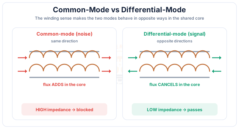
To understand a common-mode choke you must first understand the two ways noise travels on a pair of wires: common-mode and differential-mode.
| Common-mode (CM) | Differential-mode (DM) | |
|---|---|---|
| Current direction | Same on both wires | Opposite on the two wires |
| Return path | Through ground / earth | Through the other wire |
| Flux in the choke | Adds (aiding) | Cancels |
| Impedance seen | High (2L) | Low (leakage only) |
| Result | Blocked (this is the noise) | Passes (this is the signal) |
Because a common-mode choke only reacts to the difference between the two windings' flux, it is invisible to your signal but a brick wall to common-mode noise. Differential-mode noise, in contrast, is handled by X-capacitors and series inductors, not by the common-mode choke.
Schematic Symbol & Dot Convention
On a circuit diagram a common-mode choke is drawn as two coupled inductors sharing one core, with dots that mark the winding sense.
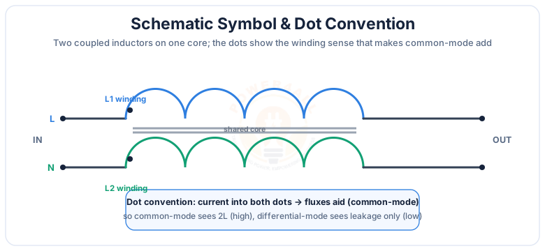
The dot convention tells you everything. When current enters both dotted ends at once (common-mode), the two magnetic fields aid, so the choke behaves like an inductor of roughly 2× a single winding — a high common-mode impedance. When current enters one dot and leaves the other (differential-mode), the fields oppose and cancel, leaving only the small leakage inductance. That is exactly the selective behaviour we want.
The Common-Mode Choke in an EMI Filter
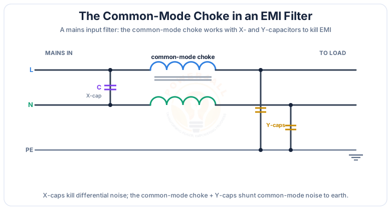
In real equipment the common-mode choke never works alone. In a mains EMI input filter it teams up with X-capacitors and Y-capacitors to attenuate all conducted EMI.
Common-mode choke
Blocks common-mode noise on L and N; the core carries no net flux for the mains current.
X-capacitor (line–neutral)
Shunts differential-mode noise; rated for across-the-line use (Class X).
Y-capacitors (to earth)
Divert common-mode noise to earth; safety-rated (Class Y) with limited leakage current.
Passes EMC tests
Together they meet conducted-emission limits such as CISPR 32 / FCC Part 15.
Common-Mode Impedance vs Frequency
A datasheet describes a common-mode choke mainly by its common-mode impedance versus frequency curve — how hard it pushes back on noise at each frequency.
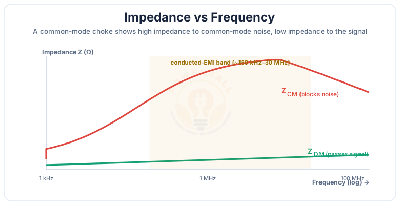
At low frequency the choke's impedance is set by its inductive reactance XL = 2πfL; higher up, core losses turn it resistive and keep the impedance high across the whole EMI band before parasitic capacitance eventually rolls it off. A good common-mode choke keeps a high impedance from about 150 kHz to 30 MHz — the conducted-EMI band regulators care about. The differential-mode curve stays low because only leakage inductance is in circuit.
How to Choose a Common-Mode Choke
Selecting a common-mode choke comes down to current rating, impedance/inductance, and core material — plus voltage rating and leakage.
Rated current
Must exceed your load current so the core does not saturate; check the temperature-rise derating.
Common-mode impedance
Pick the impedance (or inductance) that gives enough attenuation across your noise band.
Core material
Ferrite (MnZn / NiZn) for general use; nanocrystalline or amorphous for very high impedance in a small size.
Leakage inductance
Small leakage gives useful DM filtering, but keep it low on fast data lines to avoid distortion.
Voltage & isolation
Rated working voltage, creepage and clearance for mains; safety approvals where needed.
Number of lines
Two-line for single-phase; three- or four-line versions for three-phase and PE.
Rule of thumb
Start from the frequency and level of noise you must attenuate, read the impedance-vs-frequency curve for a candidate part, then confirm its rated current and saturation margin at your operating current.
Applications of Common-Mode Chokes
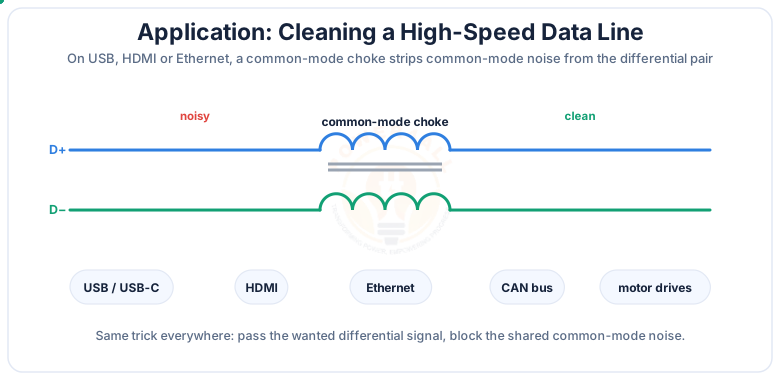
Common-mode chokes are everywhere conducted EMI has to be tamed — on power lines and high-speed data lines alike.
SMPS & adapters
The input EMI filter of every switch-mode power supply, charger and LED driver.
USB / HDMI / Ethernet
Tiny SMD common-mode chokes clean high-speed differential data lines.
Motor drives & VFDs
On inverter output cables to cut common-mode currents and bearing damage.
EV chargers & automotive
On-board chargers, traction inverters and CAN-bus lines in vehicles.
Solar inverters
Grid-tied PV inverters use common-mode chokes to meet EMC limits.
Appliances & IT
Anything that must pass CISPR / FCC conducted-emission tests.
Common-Mode Choke vs Inductor vs Transformer
A common-mode choke looks like a small transformer, but its job is different. Here is how the three compare.
| Common-mode choke | Ordinary inductor / DM choke | Transformer | |
|---|---|---|---|
| Windings | Two coupled, 1:1 | One (or series) | Two or more, turns ratio |
| Purpose | Block common-mode noise | Block any current change / DM noise | Transfer energy, change voltage |
| Signal current | Passes (flux cancels) | Opposed | Coupled to secondary |
| Core flux (normal) | ~Zero (DM cancels) | Full | Full (energy transfer) |
In short: an ordinary inductor opposes all current change, a transformer transfers power, and a common-mode choke is selective — it only chokes the common-mode part and ignores the signal.
Key Terms at a Glance
The essential common-mode-choke vocabulary engineers and students search for.
Common-mode choke
Two-winding EMI-suppression inductor.
Common-mode noise
Same-direction current on both wires.
Differential-mode
Opposite currents; the wanted signal.
Common-mode impedance
Z the choke shows to CM noise.
Leakage inductance
Small residual DM inductance.
X / Y capacitors
DM (X, L–N) & CM (Y, to earth) caps.
Frequently Asked Questions
Quick, expert answers to the questions people ask most about common-mode chokes.
What is a common-mode choke?
A common-mode choke is an EMI-suppression component with two windings on one magnetic core, placed in series with the two conductors of a circuit (line and neutral, or a data pair). It shows a high impedance to common-mode noise but almost none to the wanted differential-mode signal or power, so it filters noise without affecting the signal.
How does a common-mode choke work?
The two windings share one core. Common-mode current flows the same way on both lines, so their fluxes add, giving a high common-mode inductance that blocks the noise. Differential-mode current flows in opposite directions, so the fluxes cancel and the current passes with only a tiny leakage impedance.
What is the difference between common-mode and differential-mode noise?
Differential-mode noise flows out on one wire and back on the other, in the signal loop. Common-mode noise flows the same direction on both wires and returns via ground/earth. A common-mode choke targets common-mode noise; X-capacitors and series inductors target differential-mode noise.
What is the difference between a common-mode choke and a normal inductor?
A normal inductor is one winding that opposes any current change. A common-mode choke has two coupled windings and is selective: it strongly opposes common-mode current but lets differential-mode current pass almost freely, so it removes noise without adding series impedance to the signal path.
Common-mode choke vs differential-mode choke — what's the difference?
A common-mode choke suppresses common-mode noise with two coupled windings whose CM fluxes add. A differential-mode choke (or plain series inductor) suppresses differential-mode noise and adds impedance in the normal loop. EMI filters usually use both, plus X- and Y-capacitors.
Is a common-mode choke the same as a transformer?
No. A transformer transfers energy between windings with a turns ratio. A common-mode choke has two identical 1:1 windings that pass the differential current unchanged and choke only the common-mode current; it does not transfer power between the lines in normal use.
What is the dot convention on a common-mode choke?
The dots mark the winding sense. Current into both dots makes the fluxes aid (common-mode), so the choke shows about twice the single-winding inductance — a high impedance. Current into one dot and out the other makes the fluxes oppose (differential-mode), leaving only the small leakage inductance.
What are X and Y capacitors?
An X-capacitor sits across line and neutral to shunt differential-mode noise; Y-capacitors go from line-to-earth and neutral-to-earth to shunt common-mode noise to protective earth. With the common-mode choke they form the standard mains EMI input filter.
How do I choose a common-mode choke?
Make sure the rated current exceeds your load current (no saturation), pick the common-mode impedance/inductance that gives enough attenuation across your noise band (typically 150 kHz–30 MHz), and choose the core material — ferrite for general use, nanocrystalline/amorphous for high impedance in a small size — while checking voltage rating and leakage inductance.
What core material is used?
Usually a high-permeability ferrite toroid (MnZn for lower frequencies, NiZn for higher). For maximum attenuation in a small size, nanocrystalline or amorphous cores are used because their very high permeability gives high common-mode impedance with fewer turns.
Where are common-mode chokes used?
In SMPS input filters, chargers and LED drivers; on USB, HDMI, Ethernet and CAN-bus data lines; on motor-drive and inverter cables; in EV chargers, automotive electronics, solar inverters and appliances — anywhere equipment must pass CISPR / FCC conducted-emission limits.
Does a common-mode choke cause insertion loss to the signal?
Ideally very little — differential-mode current sees only the small leakage inductance, so the signal or power passes with negligible loss. A little leakage even adds useful differential-mode filtering, but on high-speed data lines it should be kept small to avoid distorting the signal.
Conclusion & Key Takeaways
A common-mode choke is the selective filter at the heart of EMI suppression: it blocks the noise that flows the same way on both wires and ignores the signal that flows the opposite way.
Two windings, one core
A coupled 1:1 inductor.
CM flux adds
High Z → noise blocked.
DM flux cancels
Low Z → signal passes.
EMI filter
With X- & Y-capacitors.
150 kHz–30 MHz
High CM impedance band.
Everywhere
SMPS, USB, drives, EVs.