EMI / Line Filter
The complete guide to the mains EMI filter (line filter) — the passive low-pass network on an AC input that blocks conducted electromagnetic interference. Learn how it works, its circuit of X-capacitors, Y-capacitors and a common-mode choke, common-mode vs differential-mode noise, insertion loss, and the EMC standards (CISPR 32, EN 55032, FCC Part 15) it helps you pass.
Complete Learning Path — EMI / Line Filter
From what it is and how it works, to the circuit, noise types, insertion loss, EMC standards, selection and applications
What is an EMI / Line Filter?
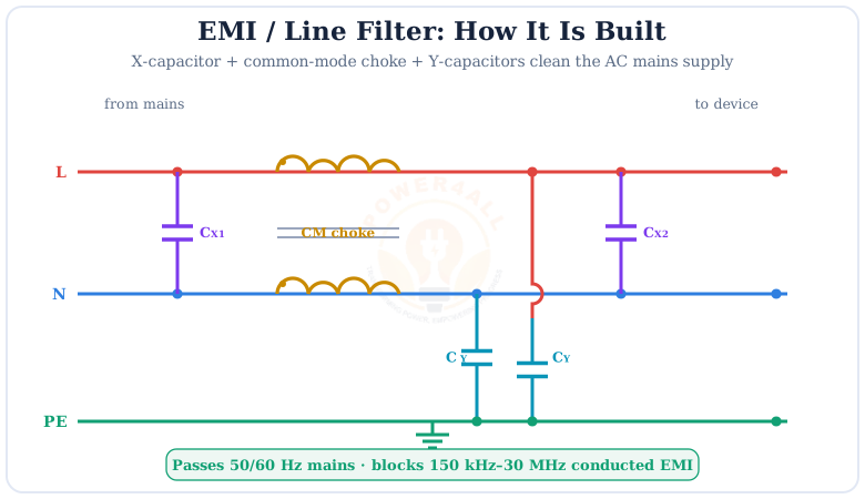
An EMI filter — also called a line filter, mains filter or RFI filter — is a passive low-pass filter fitted on the AC mains input of equipment. Its job is to block high-frequency conducted electromagnetic interference (EMI) from travelling between the device and the power line, in both directions, while letting the 50/60 Hz supply pass untouched.
Nearly every modern electronic product — a switch-mode power supply, computer, LED driver, TV, motor drive or appliance — switches current at high frequency and so generates mains noise. A line filter cleans that noise so the product meets EMC (electromagnetic compatibility) limits and does not disturb its neighbours. It is built from capacitors and a common-mode choke.
EMI vs RFI
EMI (electromagnetic interference) and RFI (radio-frequency interference) mean much the same thing here — unwanted high-frequency energy on the mains. A “line filter”, “EMI filter” and “RFI filter” all refer to the same mains-input suppression network.
EMI Basics: Conducted vs Radiated
Electromagnetic interference travels two ways, and the line filter deals with one of them: conducted emissions that ride along the power cable.
| Type | Path | Frequency band | Fixed by |
|---|---|---|---|
| Conducted EMI | Along the mains wires | 150 kHz – 30 MHz | Line filter (X/Y caps, CM choke) |
| Radiated EMI | Through the air as waves | 30 MHz – 1 GHz+ | Shielding, layout, grounding |
Below ~30 MHz, noise mostly travels conducted along the cable — exactly what a line filter attenuates. Above 30 MHz it becomes mainly radiated, handled by shielding and PCB layout. The filter also blocks incoming noise, protecting the device from a dirty supply. High-frequency switching in power electronics and rich harmonics are common EMI sources.
Why it’s a low-pass filter
The supply you want is low-frequency (50/60 Hz); the noise you don’t want is high-frequency (kHz–MHz). A low-pass network is the natural fit: pass the low, block the high — using inductive and capacitive reactance.
Common-Mode vs Differential-Mode Noise
To filter noise you must know how it flows. Conducted EMI comes in two flavours, each tackled by different filter parts.
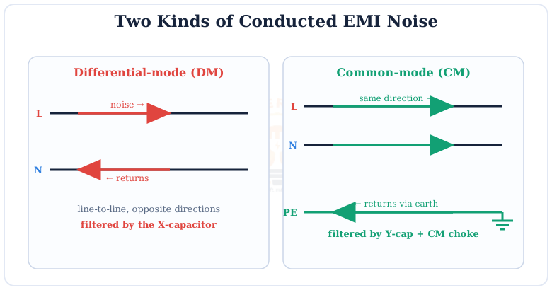
Differential-mode (DM)
Noise between line and neutral, opposite directions. Filtered by the X-capacitor (and DM inductance).
Common-mode (CM)
Noise on both lines together, returning via earth. Filtered by the Y-capacitors and common-mode choke.
The Common-Mode Choke
The heart of the filter is the common-mode choke: two windings on one core that block noise but wave the mains through.
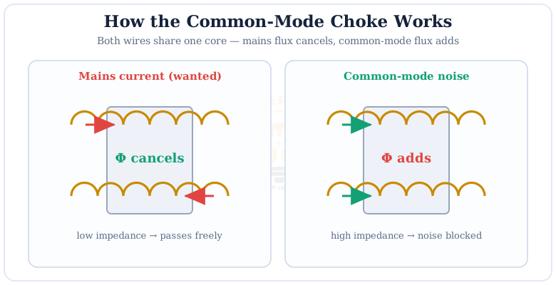
Because the wanted line and neutral currents are equal and opposite, their magnetic fluxes in the shared core cancel — so the choke barely resists the supply and stays cool. Common-mode noise, flowing the same way in both windings, makes the fluxes add, so the choke presents a high impedance that chokes the noise off. This is why it is called a common-mode choke.
Leakage inductance helps too
A real CM choke also has a little leakage inductance that acts as differential-mode inductance, giving the X-capacitors a hand against DM noise — a useful bonus from a single component.
X-Capacitors & Y-Capacitors
The two safety capacitor classes do different jobs and carry different safety ratings — getting them right is critical.
| Capacitor | Connected | Filters | Safety class | Typical value |
|---|---|---|---|---|
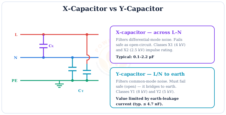
| X-capacitor | Across line–neutral | Differential-mode | X1 (4 kV), X2 (2.5 kV) | 0.1 – 2.2 μF |
| Y-capacitor | Line/neutral to earth | Common-mode | Y1 (8 kV), Y2 (5 kV) | 1 – 4.7 nF |
Never use an ordinary capacitor
Only rated class-X and class-Y safety capacitors may be used. A Y-capacitor bridges live to earth, so its value is capped by the allowed earth-leakage current (a shock-safety limit). Both types are designed to fail open, never short.
Insertion Loss: Measuring Performance
A filter’s effectiveness is quoted as insertion loss in decibels (dB) — how much noise it removes across frequency. More dB means better suppression.
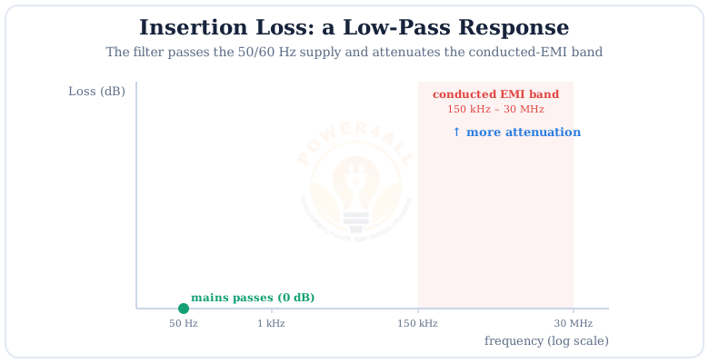
Datasheets give separate common-mode and differential-mode insertion-loss curves, because the two noise types are attenuated by different parts of the filter. Engineers compare these curves against the target standard’s limit line, with margin, to confirm the design will pass a conducted-emissions test.
Where It Fits & EMC Standards
The line filter sits right at the mains inlet, between the noisy device and the grid — the last line of defence before emissions reach the power network.
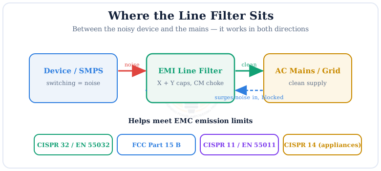
Regulators cap how much conducted noise a product may inject into the mains. Key standards include CISPR 32 / EN 55032 (multimedia equipment), CISPR 11 / EN 55011 (industrial, scientific & medical), CISPR 14 (household appliances), the older CISPR 22 (IT equipment), and FCC Part 15 Subpart B in the USA. Meeting their conducted-emission limits is the usual reason a line filter is fitted at all.
How to Select an EMI Line Filter
Picking the right filter is a balance of rating, performance and safety.
Voltage & current rating
Match the mains voltage (e.g. 250 VAC) and the load current with margin for heating.
Insertion loss
Enough CM and DM attenuation across the band to meet your standard with margin.
Leakage current
Y-cap value sets earth-leakage — keep it under the safety limit (often < 3.5 mA).
Single vs two-stage
Noisier loads may need a two-stage (π) filter for extra attenuation.
Applications of Line Filters
EMI line filters appear at the mains inlet of almost anything with a switching converter inside.
SMPS & adapters
Computer, phone and laptop power supplies use an input filter to pass EMC tests.
Motor drives (VFDs)
Variable-frequency drives fit line filters to curb switching noise on the supply.
LED drivers & lighting
Electronic LED and fluorescent drivers need filtering to stay within limits.
Appliances & industrial
Inverter appliances, welders and instruments use filters for CISPR compliance.
Key Terms at a Glance
The essential EMI / line-filter vocabulary engineers and students search for.
EMI / line filter
Mains low-pass noise filter.
X-capacitor
Across L–N; filters DM noise.
Y-capacitor
L/N to earth; filters CM noise.
CM choke
Coupled coils; blocks CM noise.
Insertion loss
Attenuation in dB vs frequency.
Conducted EMI
150 kHz–30 MHz on the cable.
Frequently Asked Questions
Quick, expert answers to the questions people ask most about EMI / line filters.
What is an EMI / line filter?
A passive low-pass filter on the AC mains input of a device that blocks high-frequency conducted electromagnetic interference (EMI) from passing between the equipment and the mains in both directions, while letting the 50/60 Hz supply through. It contains X-capacitors, Y-capacitors and a common-mode choke.
How does an EMI line filter work?
As a low-pass filter. The common-mode choke gives high impedance to high-frequency noise while the X- and Y-capacitors shunt noise currents away. Together they pass 50/60 Hz but attenuate the 150 kHz–30 MHz conducted-EMI band. The choke is wound so the wanted mains flux cancels but common-mode noise sees high impedance.
Common-mode vs differential-mode noise — what’s the difference?
Differential-mode noise flows in opposite directions on line and neutral (line-to-line) and is suppressed mainly by the X-capacitor. Common-mode noise flows the same way on both lines and returns via earth; it is suppressed by the Y-capacitors and the common-mode choke.
What is the difference between an X-capacitor and a Y-capacitor?
An X-capacitor connects across line–neutral and filters differential-mode noise (class X1 4 kV, X2 2.5 kV). A Y-capacitor connects from line/neutral to protective earth and filters common-mode noise (class Y1 8 kV, Y2 5 kV); it must fail open and its value is limited by earth-leakage current.
What is a common-mode choke?
Two windings on one magnetic core, one in line and one in neutral. Wanted mains current makes fluxes that cancel, so the choke adds little impedance. Common-mode noise makes fluxes that add, so the choke gives high impedance and blocks the noise.
What is the conducted-EMI frequency range?
Conducted emissions are generally regulated from 150 kHz to 30 MHz under CISPR and FCC rules — the band a line filter is designed to attenuate. Above ~30 MHz emissions become mainly radiated and are handled by shielding and layout.
What is insertion loss?
How much a filter attenuates a signal, in decibels, compared with no filter. A line filter has near-zero insertion loss at 50/60 Hz (supply passes) and high insertion loss across the conducted-EMI band (noise blocked). More dB means better suppression.
Which standards require an EMI line filter?
Conducted-emission limits appear in CISPR 32 / EN 55032 (multimedia), CISPR 11 / EN 55011 (industrial/ISM), CISPR 14 (appliances), the older CISPR 22 (IT), and FCC Part 15 Subpart B (USA). A line filter is the usual way to meet them.
Why do SMPS need a line filter?
A switch-mode power supply switches at high frequency and generates strong conducted EMI on the mains. Without a line filter this noise would exceed EMC limits and disturb other equipment, so a filter is fitted at the SMPS input to suppress it and pass certification.
Does a line filter protect against surges?
Mainly it suppresses continuous high-frequency noise, not large surges. It attenuates fast transients somewhat, but real surge protection needs dedicated surge-protective devices (MOVs, gas discharge tubes). Filters and surge protectors are often used together.
Conclusion & Key Takeaways
The EMI / line filter is the small but essential network that keeps a product’s switching noise off the mains — and the mains’ noise out of the product.
Low-pass filter
Passes 50/60 Hz, blocks kHz–MHz.
X-capacitor
Across L–N; DM noise.
Y-capacitor
To earth; CM noise.
CM choke
Flux cancels for mains.
Insertion loss
Performance in dB.
EMC standards
CISPR 32, FCC Part 15.