Gate Driver IC
The muscle between your controller and the power stage. A gate driver IC turns a weak PWM signal into amps of fast gate current so a power MOSFET or IGBT switches cleanly. Learn why it's needed, low-side vs high-side, the bootstrap supply, half-bridge dead-time, the gate resistor, isolated drivers and the IR2110.
Complete Learning Path — Gate Driver IC
From what it is and why it's needed, to low-side / high-side / half-bridge drivers, the bootstrap supply, the gate resistor, isolation, key specs, the IR2110 and applications
What is a Gate Driver IC?
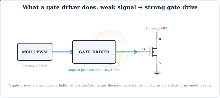
A gate driver IC is a fast current buffer and level shifter that sits between a controller (a microcontroller or PWM chip) and the gate of a power MOSFET or IGBT. It delivers the strong, quick pulse of current the gate needs to switch cleanly.
The controller decides when to switch; the gate driver provides the muscle to actually do it fast.
Why It's Needed
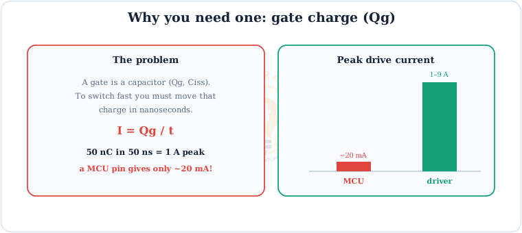
A MOSFET/IGBT gate is essentially a capacitor (its gate charge, Qg). To switch fast you must move that charge in nanoseconds — which needs a big current pulse a controller simply can't supply.
How It Drives the Gate
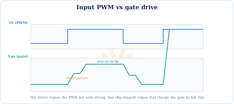
The driver copies the input PWM but delivers strong, fast edges. The gate voltage VGS ramps up (its slope set by the gate resistor), pauses at the Miller plateau, then reaches full drive.
Low-Side Driver
The simplest case: the MOSFET's source is at ground, so the driver output just swings between 0 and VCC.

High-Side Driver & Bootstrap
When the MOSFET's source floats (as at a bridge switch node), the driver needs a floating supply above the source. The clever, cheap trick is a bootstrap capacitor and diode.

Keep it switching
A bootstrap supply only recharges when the low side turns on, so a pure high-side switch that stays on forever needs a different supply (charge pump or isolated). For normal PWM it works perfectly.
Half-Bridge Driver
One chip drives both a high-side and a low-side MOSFET — the totem-pole at the heart of every inverter and buck/boost stage.

Shoot-through
If both MOSFETs are ever ON together, the supply is shorted through them — a destructive shoot-through current. Dead-time (a brief both-off gap) is what stops it.
The Gate Resistor (Rg)
A small resistor between the driver and the gate sets the switching speed — and trades it against EMI and ringing.

Isolated Gate Drivers
For high-voltage and mains-connected stages, an isolated gate driver puts a safety barrier between the control side and the power side.
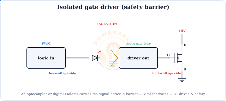
Isolation protects the low-voltage electronics (and the user) from the high-voltage power stage, and breaks ground loops in large systems. It is a must for motor drives, solar inverters and EV power stages.
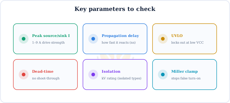
Key Parameters
Pick a driver by these specs — they decide how fast, how safe and how robust your power stage is.
Gate Driver ICs & Pinout
The IR2110 is the classic high-and-low-side driver; single low-side parts like the TC4420 and UCC27511 are everywhere too.
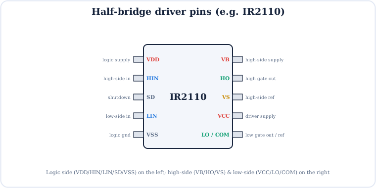
IR2110 / IR2104
High + low side (half-bridge), bootstrap, with dead-time (IR2104).
TC4420 / UCC27511
Fast single low-side drivers for one MOSFET.
Si823x / isolated
Reinforced isolation for mains & IGBT drives.
Applications
Wherever power is switched at speed, a gate driver is in the loop.
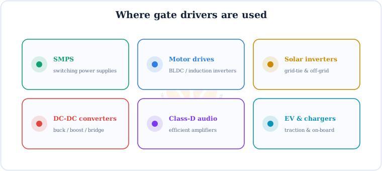
SMPS
Switching power supplies & adapters.
Motor drives
BLDC and induction inverters.
Solar inverters
Grid-tie and off-grid.
DC-DC
Buck, boost and bridge converters.
Class-D audio
High-efficiency amplifiers.
EV & chargers
Traction and on-board chargers.
Key Terms — Glossary
| Term | Meaning |
|---|---|
| Gate driver IC | Current buffer/level shifter that drives a MOSFET/IGBT gate. |
| Gate charge (Qg) | Charge needed to switch the gate; sets the drive current. |
| Low-side | Drives a switch whose source is at ground. |
| High-side | Drives a switch whose source floats; needs a floating supply. |
| Bootstrap | Capacitor + diode that make the floating high-side supply. |
| Half-bridge | High-side + low-side switches driven together. |
| Dead-time | Both-off gap that prevents shoot-through. |
| Shoot-through | Destructive current when both bridge switches are on. |
| Gate resistor (Rg) | Sets switching speed; trades loss vs EMI/ringing. |
| UVLO | Under-voltage lockout — disables drive at low supply. |
| Miller plateau | Flat part of VGS during switching. |
Frequently Asked Questions
Quick, expert answers to the questions people ask most about gate drivers.
What is a gate driver IC?
A chip that takes a weak logic/PWM signal and delivers the strong, fast current pulse needed to switch a power MOSFET or IGBT gate. It is a fast current buffer and level shifter between a controller and the power switch.
Why can a microcontroller not drive a MOSFET directly?
The gate is a capacitor with charge Qg. Switching fast means moving that charge in nanoseconds, needing amps of peak current, but an MCU pin only gives tens of milliamps — so the MOSFET switches slowly and overheats.
Low-side vs high-side gate driver?
A low-side driver switches a MOSFET with its source at ground (output swings 0→VCC). A high-side driver switches one whose source floats, so it needs a floating supply, usually a bootstrap capacitor and diode.
What is a bootstrap circuit?
A capacitor and diode that make a floating supply for the high-side output. When the switch node is low, the cap charges through the diode; when the node swings high, the cap floats up and powers the high-side gate.
What is dead-time in a half-bridge?
A short delay when both MOSFETs are off, so they never conduct together and short the supply (shoot-through). Half-bridge drivers add dead-time automatically.
What does the gate resistor Rg do?
It sets switching speed by limiting gate current. Smaller Rg = faster and lower loss but more EMI/ringing; larger = slower and cleaner. A diode split can set turn-on and turn-off speeds separately.
What is an isolated gate driver?
One that carries the signal across an isolation barrier (optocoupler or digital isolator), separating the low-voltage control side from the high-voltage power side. Essential for mains IGBT drives and safety.
What are common gate driver ICs?
IR2110 and IR2104 (half-bridge), TC4420 and UCC27511 (single low-side), and Si823x-family isolated drivers. Choose by peak current, driver type, and whether you need isolation.
Conclusion & Key Takeaways
A gate driver is the essential link that lets a small controller switch big power fast, efficiently and safely.
Current buffer
Amps to charge the gate.
I = Qg/t
Why an MCU can't.
Low / high-side
Bootstrap for high-side.
Dead-time
No shoot-through.
Rg
Speed vs EMI.
Isolation
Safety at high voltage.