Complete Learning Path — Series-Parallel Circuits
From spotting groups and reducing step by step, to worked examples, ladder networks and the loaded voltage divider
What is a Series-Parallel Circuit?
A series-parallel circuit is a network that contains both series and parallel connections at once. Some components share one path (series); others sit on branches across the same two nodes (parallel). Almost every real circuit is series-parallel.
The good news: you never need a new formula. You solve a combined network by reduction — repeatedly replacing series and parallel groups with single equivalent resistances until only one is left. Then Ohm's law gives every current and voltage.
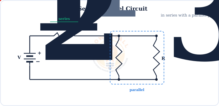
The whole method in one line
Combine parallel groups → combine series chains → repeat → find total current → work backwards for each branch. That's it.
Step 1: Spotting Series and Parallel Groups
Before any maths, look at the nodes. The test is about connections, not appearance.
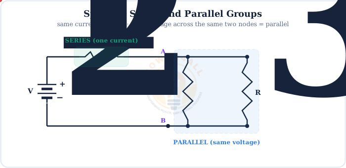
Series test
Same current flows through both, with no branch point between them.
Parallel test
Both ends join the same two nodes, so the same voltage sits across each.
Don't judge by the drawing
Components can look parallel but share a node with something else. Always follow the wires to the nodes: same current = series, same voltage across the same nodes = parallel.
Step 2: Reduce the Network Step by Step
Collapse the circuit one group at a time. The golden order is parallel first, then series — work from the parts furthest from the source inward.
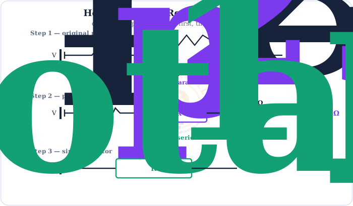
Parallel: 1/Rp = 1/R2 + 1/R3 · Series: Rtotal = R1 + Rp
Combine each parallel group, then add the series chain — repeat until one resistance remains
Product-over-sum shortcut
For exactly two parallel resistors, skip the reciprocals: Rp = (R2 × R3) / (R2 + R3). Here (6×3)/(6+3) = 2 Ω.
Step 3: A Full Worked Example
Once the circuit is a single resistance, Ohm's law unlocks everything. Here is the complete solution for the network above on a 12 V supply.
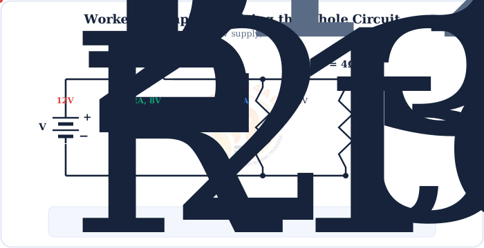
Worked example — 12 V, R1=4 Ω, R2=6 Ω, R3=3 Ω
1. Parallel: Rp = (6×3)/(6+3) = 2 Ω
2. Series total: Rtotal = 4 + 2 = 6 Ω
3. Total current (through R1): I = 12/6 = 2 A
4. Voltages: VR1 = 2×4 = 8 V, so the pair gets 12 − 8 = 4 V
5. Branch currents: I2 = 4/6 = 0.67 A, I3 = 4/3 = 1.33 A → check 0.67+1.33 = 2 A ✓
Ladder Networks
A ladder network is a repeating series-parallel pattern of series rungs and parallel shunts. It looks intimidating but reduces with the same two moves.
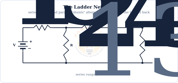
Always begin at the end furthest from the source, where a shunt and a series resistor can be combined first. Each combination shortens the ladder by one rung, until a single equivalent resistance faces the source. Ladder networks appear in R-2R digital-to-analog converters, attenuators and filter chains.
A Real Example: The Loaded Voltage Divider
Here is where series-parallel really matters in practice. A plain voltage divider is two series resistors — but connect a load and it becomes a series-parallel circuit.
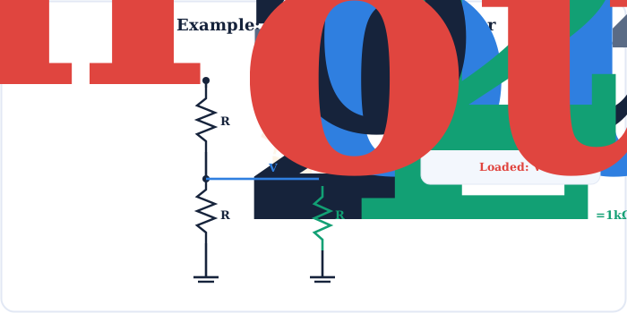
Vout = Vin × (R2 ∥ RL) / (R1 + (R2 ∥ RL))
A loaded divider — replace R2 with its parallel combination with the load
Why "no-load" divider maths can fool you
Design a divider ignoring the load and the real output will be lower than expected. This loading effect is exactly why dividers are made from low resistances (stiff) or buffered with an op-amp when driving a real load.
Series, Parallel & Series-Parallel at a Glance
Keep the rules for each connection type straight and combined networks become routine.
| Property | Series part | Parallel part |
|---|---|---|
| Current | Same through all | Divides between branches |
| Voltage | Divides across each | Same across each branch |
| Combine as | R1+R2+… | 1/R1+1/R2+… |
| Effect on total | Increases resistance | Decreases resistance |
| Solve order | Reduce the innermost/farthest groups first — parallel, then series — and repeat | |
Problem-Solving Tips & Common Mistakes
A few habits make series-parallel problems fast and error-free.
Redraw it
Sketch each reduction stage — a cleaner drawing reveals the next group.
Label the nodes
Name junctions (A, B, C). Same two nodes = parallel; in a chain = series.
Use reciprocals
Never add parallel resistances directly — use 1/R or product-over-sum.
Check with KCL/KVL
Branch currents must add to the total; voltage drops must add to the supply.
The #1 mistake
Adding two parallel resistors as if they were in series. 6 Ω ∥ 3 Ω is 2 Ω, not 9 Ω — parallel always gives less than the smallest.
Key Terms at a Glance
The essential series-parallel vocabulary students and engineers search for.
Series-parallel
A network with both connection types.
Reduction
Collapsing groups to one resistance.
Equivalent resistance
Single R that replaces a group.
Node
A junction where wires meet.
Ladder network
Alternating rungs and shunts.
Loading effect
A load pulling a divider's output down.
Frequently Asked Questions
Quick, expert answers to the questions people ask most about series-parallel circuits.
What is a series-parallel circuit?
A series-parallel circuit is a network that contains both series and parallel connections in the same circuit. Some components share a single path (series) while others sit on branches across the same two nodes (parallel). Most real circuits are series-parallel.
How do you solve a series-parallel circuit?
Reduce it step by step. First combine each parallel group into a single equivalent resistance, then add up the series resistances, repeating until the whole circuit becomes one equivalent resistor. Find the total current with Ohm's law, then work backwards to get each branch current and voltage.
How do you know if two resistors are in series or parallel?
Two components are in series if the same current flows through both, with no branch point between them. They are in parallel if both ends connect to the same two nodes, so the same voltage appears across each. Same current means series; same voltage across the same nodes means parallel.
How do you find the total resistance of a series-parallel circuit?
Collapse the network in stages. Replace each parallel group using 1/R = 1/R1 + 1/R2 (or product over sum for two), then add the resulting series resistances. Repeat until a single equivalent resistance remains — that is the total resistance seen by the source.
Solve a 4 Ω resistor in series with 6 Ω parallel 3 Ω.
First the parallel pair: 6 ∥ 3 = (6×3)/(6+3) = 2 Ω. Then add the series resistor: 4 + 2 = 6 Ω total. On a 12 V supply the current is 12/6 = 2 A.
What is a ladder network?
A ladder network is a repeating series-parallel structure of series resistors (rungs) and parallel resistors (shunts). It is solved from the far end back toward the source, combining the last shunt and series resistor at each step until one equivalent remains.
Why does adding a load reduce a voltage divider's output?
A load connected across the lower resistor puts it in parallel, lowering that part of the divider. Since the lower resistance drops, its share of the voltage drops too, so the output falls. For example, a 1 k load across a 1 k lower resistor halves it to 0.5 k and pulls a 6 V output down to 4 V.
Can current and voltage both divide in the same circuit?
Yes. In a series-parallel circuit the voltage divides across the series parts while the current divides among the parallel branches. The two rules apply to different sections of the same network at the same time.
What is the difference between series, parallel and series-parallel?
A series circuit has one path; a parallel circuit has branches across the same nodes; a series-parallel circuit combines both. You solve series-parallel circuits by breaking them into series and parallel sub-groups and reducing each in turn.
What are common mistakes when solving series-parallel circuits?
Common mistakes are: labelling components series or parallel by how they look rather than by their nodes, adding parallel resistances directly instead of using reciprocals, forgetting that the parallel group's voltage is shared, and not checking that the branch currents add back to the total.
Conclusion & Key Takeaways
Series-parallel circuits look complex but yield to one simple habit: break them into groups and reduce, one step at a time.
Both types
Series and parallel together.
Check nodes
Same current vs same voltage.
Parallel first
Then add the series chain.
One resistance
Then Ohm's law for I.
Back-solve
Each branch V and I.
Check
KCL & KVL must balance.