ESP8266 NodeMCU
The board that made Wi-Fi cheap enough for every hobby project. The ESP8266 packs a 32-bit CPU and 2.4 GHz Wi-Fi into one tiny chip, and the NodeMCU board makes it plug-and-play over USB. This guide covers the board anatomy, the ESP-12E module, a complete pinout with the D-pin to GPIO mapping, the tricky boot pins, A0, PWM, Wi-Fi and deep sleep. It finishes with code examples and beginner projects.
Complete Learning Path — ESP8266 NodeMCU
From the board, module and chip, to a full pinout with every pin, safe and boot pins, power, analog, PWM, buses, Wi-Fi, deep sleep, uploading, code and projects
What is the ESP8266 NodeMCU?
The ESP8266 is a low-cost Wi-Fi microcontroller from Espressif Systems. It has a 32-bit processor at 80 MHz (160 MHz if you ask) and a full 2.4 GHz Wi-Fi radio on one chip. The NodeMCU is the open-source development board that puts it on a breadboard-friendly PCB with USB programming.
When it appeared in 2014, the ESP8266 cut the cost of adding Wi-Fi to a project to a few dollars. It is still one of the most popular chips for smart plugs, sensor loggers, web-controlled relays and home-automation gadgets. The most common board is the NodeMCU v1.0 (ESP-12E, CP2102). The wider LoLin “v3” uses a CH340 but has the same pinout.
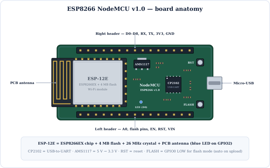
Parts of the NodeMCU board
ESP-12E
The shielded module: ESP8266EX chip, 4 MB flash, a 26 MHz crystal and the PCB antenna.
CP2102 / CH340
The USB-to-UART bridge. It carries uploads and the Serial Monitor over USB.
AMS1117-3.3
A 3.3 V LDO regulator that turns the 5 V from USB or VIN into 3.3 V.
RST button
Resets the chip and restarts your sketch.
FLASH button
Pulls GPIO0 LOW to enter flash mode (uploads normally do this automatically). You can also read it as a button (D3).
The ESP-12E Module
The metal can on the NodeMCU is the ESP-12E, a 16 × 24 mm module with 22 castellated pads. It holds the ESP8266EX chip, a 4 MB SPI flash, a 26 MHz crystal and a meander PCB antenna.
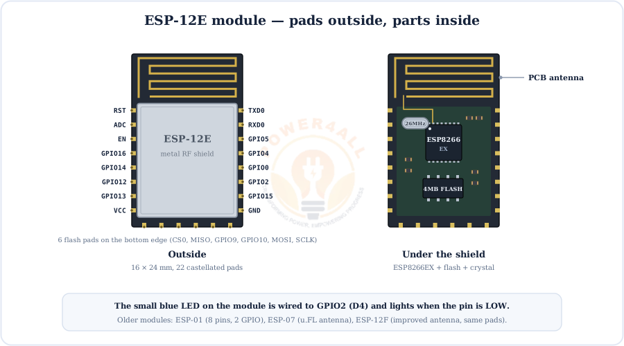
- ESP-01: the tiny 8-pin module with only GPIO0 and GPIO2 broken out, often used as a Wi-Fi add-on for Arduino.
- ESP-12E / ESP-12F: the full 22-pad modules used on NodeMCU and Wemos D1 mini. The 12F has a slightly better antenna.
- ESP-07: adds a u.FL connector for an external antenna.
Inside the ESP8266EX Chip
The ESP8266EX pairs a single Tensilica L106 32-bit RISC core with a complete Wi-Fi MAC, radio and a small set of peripherals.
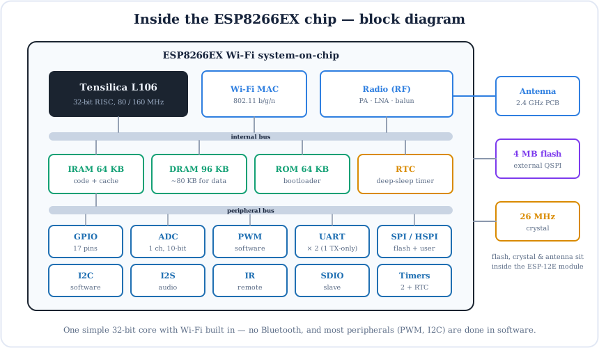
- CPU: 80 MHz by default, 160 MHz selectable. The Wi-Fi stack shares this core, so call
delay()oryield()in long loops, or the watchdog resets the chip. - Memory: your program runs from external flash through a cache. About 80 KB of RAM is left for data, with roughly 40–50 KB free once Wi-Fi is running.
- Peripherals: one 10-bit ADC, two UARTs (one TX-only) and a hardware SPI. PWM and I2C run in software on any pin.
Full ESP8266 NodeMCU Pinout
Here is the complete 30-pin NodeMCU v1.0 pinout. Each pin shows its board label (D0, D1…), the real GPIO number and its functions: I2C, SPI, UART, boot, wake and flash.
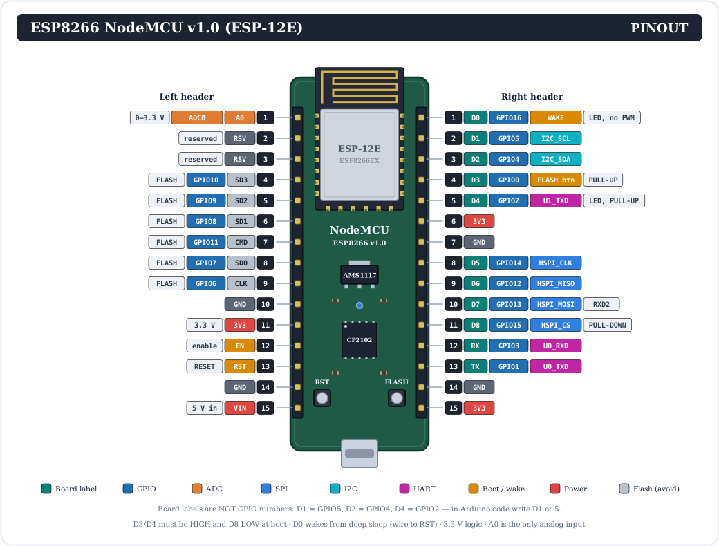
Here is the same information as a quick colour map:
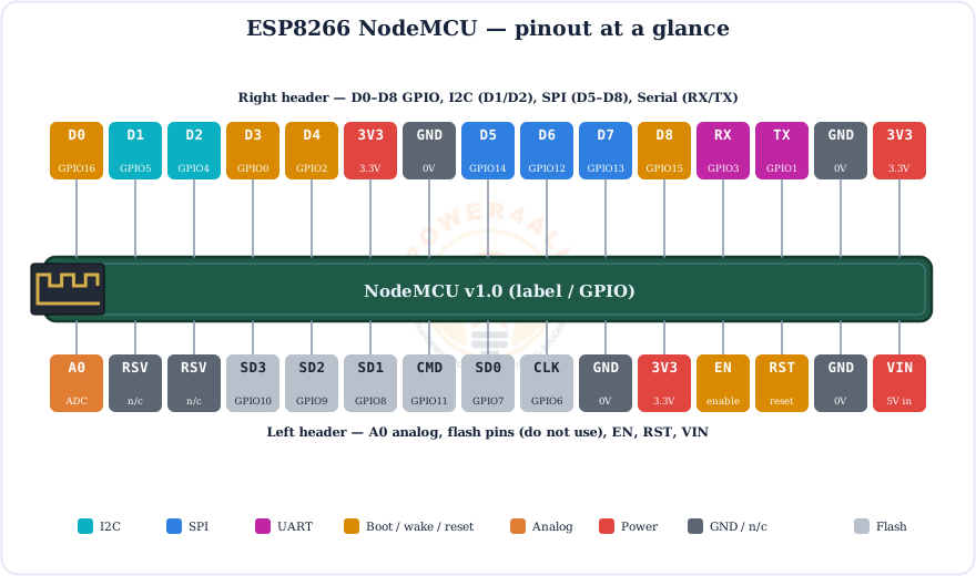
D-pin to GPIO mapping
| Board label | GPIO | Main use | Notes |
|---|---|---|---|
| D0 | GPIO16 | Deep-sleep wake, on-board LED | No PWM, no interrupts, no I2C |
| D1 | GPIO5 | I2C SCL | Safe |
| D2 | GPIO4 | I2C SDA | Safe |
| D3 | GPIO0 | FLASH button | Must be HIGH at boot |
| D4 | GPIO2 | Module LED, UART1 TX | Must be HIGH at boot |
| D5 | GPIO14 | SPI SCK | Safe |
| D6 | GPIO12 | SPI MISO | Safe |
| D7 | GPIO13 | SPI MOSI | Safe |
| D8 | GPIO15 | SPI CS | Must be LOW at boot |
| RX | GPIO3 | UART0 RX (USB) | Used by Serial |
| TX | GPIO1 | UART0 TX (USB) | Used by Serial |
| A0 | ADC0 | Analog input | 0–3.3 V → 0–1023 |
Every NodeMCU Pin Explained
Now let's look at what each group of pins does. In Arduino code you can use either the board label (D1) or the GPIO number (5).
Power & control pins
| Pin | What it does |
|---|---|
| VIN | 5 V input (or USB 5 V out). It feeds the AMS1117 regulator. |
| 3V3 | Regulated 3.3 V for sensors. There are three 3V3 pins. |
| GND | Ground. There are four GND pins; connect all grounds together. |
| EN | Chip enable (pulled HIGH). Take it LOW to switch the chip off. |
| RST | Reset (active LOW), the same as the RST button. Wire it to D0 for deep-sleep wake. |
| RSV | Reserved, not connected. |
GPIO pins
All D-pins work with pinMode(), digitalWrite() and digitalRead() at 3.3 V logic. GPIO0–15 have internal pull-ups (INPUT_PULLUP). GPIO16 (D0) only has a pull-down (INPUT_PULLDOWN_16). Keep each pin to about 12 mA and switch relays or motors through a transistor or MOSFET.
D0 (GPIO16)
Wired to the RTC. It wakes the chip from deep sleep when connected to RST. No PWM, interrupts or I2C. It also drives the board's own LED.
D1 & D2
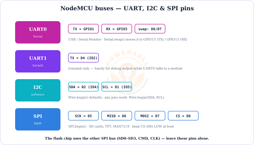
The default I2C pins: D1 = SCL, D2 = SDA. They are the two most useful pins on the board.
D3, D4, D8
Boot-strapping pins, with 10k pull-ups on D3/D4 and a pull-down on D8. They are OK for outputs and buttons that don't change their boot level.
D5–D8
The hardware HSPI bus: SCK, MISO, MOSI, CS. SD cards, TFTs and MAX7219 displays go here.
D4 LED
The blue LED on the ESP-12E is on GPIO2 and is active-LOW: digitalWrite(LED_BUILTIN, LOW) turns it on.
SD0–SD3, CMD, CLK
GPIO6–11 are the flash chip's SPI pins. Don't connect anything to them.
Which NodeMCU Pins Are Safe to Use?
The NodeMCU has fewer free pins than it seems. This chart sorts them:
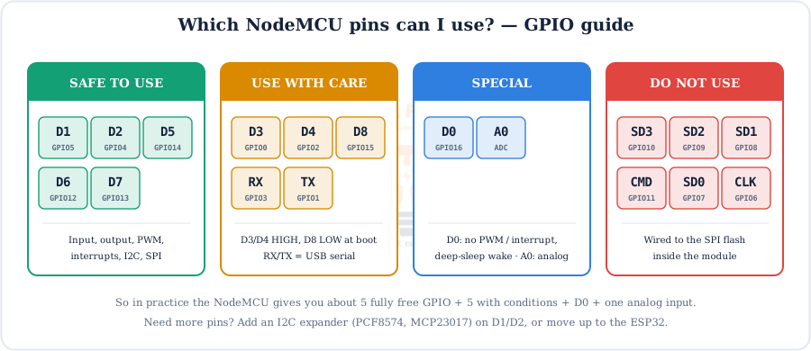
Running out of pins?
Put an I2C expander (PCF8574 or MCP23017) on D1/D2 for 8–16 extra pins, use an ADS1115 for more analog inputs, or step up to the ESP32, which has about 25 usable GPIO.
Boot Modes & Strapping Pins
At every reset the ESP8266 reads GPIO15, GPIO0 and GPIO2 to decide how to boot. Getting this wrong is the most common reason a NodeMCU project “won't start”.
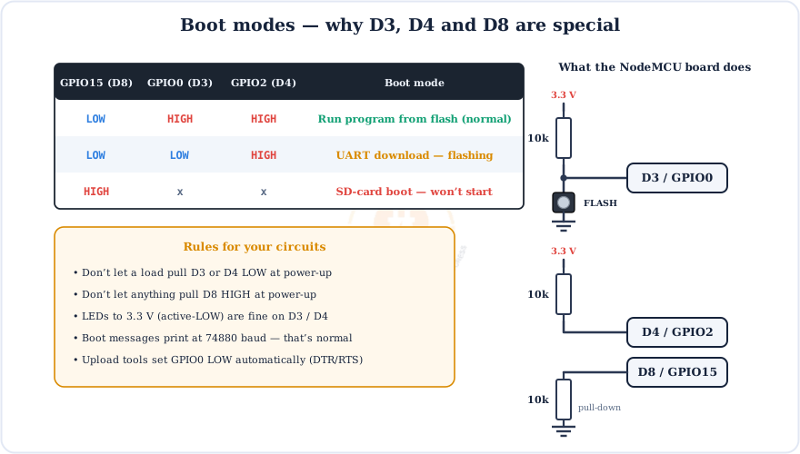
Classic boot traps
A relay module whose input pulls D3 or D4 LOW, a sensor that drives D8 HIGH, or a big capacitor on these pins can all stop the board from booting. Move such loads to D1, D2, D5, D6 or D7.
Powering the NodeMCU
Feed the board 5 V through USB or VIN. The AMS1117 regulator makes the 3.3 V the ESP8266 needs.
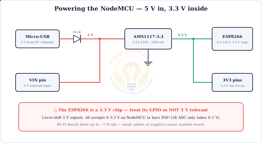
3.3 V logic
Treat the GPIO as not 5 V tolerant. For 5 V sensors such as the HC-SR04, use a level shifter or a 1k/2k divider on the signal going into the NodeMCU. Wi-Fi bursts draw ~170 mA, so use a solid supply and a short, thick USB cable.
Analog Input A0
The ESP8266 has just one 10-bit ADC. On the NodeMCU it is the A0 pin, and analogRead(A0) returns 0–1023.
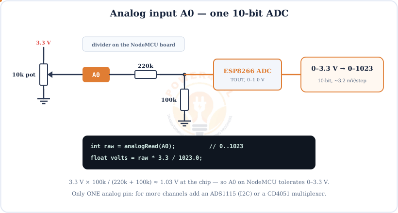
Bare ESP-12 modules and some other boards have no divider, so their ADC only accepts 0–1.0 V. Check before connecting 3.3 V. You can also read the supply voltage with ADC_MODE(ADC_VCC) and ESP.getVcc(), but then A0 can't be used for sensors.
PWM Output
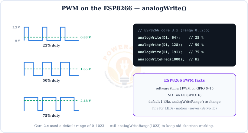
The ESP8266 makes PWM in software on any GPIO except D0. Use analogWrite(pin, 0…255). The default frequency is 1 kHz (see pulse & PWM signals).
// fade an LED on D1
void setup() { pinMode(D1, OUTPUT); }
void loop() {
  for (int d = 0; d <= 255; d++) { analogWrite(D1, d); delay(4); }
  for (int d = 255; d >= 0; d--) { analogWrite(D1, d); delay(4); }
}
ESP8266 Arduino core 3.x uses a 0–255 range like an Uno. Core 2.x used 0–1023; call analogWriteRange(1023) if an older sketch looks too bright.
Communication: UART, I2C & SPI
The NodeMCU has a full UART0 (USB), a transmit-only UART1, software I2C on any pins, and the hardware HSPI bus.
// scan the I2C bus on D2 (SDA) / D1 (SCL)
#include <Wire.h>
void setup() {
  Serial.begin(115200);
  Wire.begin(D2, D1);
  for (byte a = 1; a < 127; a++) {
    Wire.beginTransmission(a);
    if (Wire.endTransmission() == 0) Serial.printf("Found device at 0x%02X\n", a);
  }
}
void loop() {}
Wi-Fi on the ESP8266
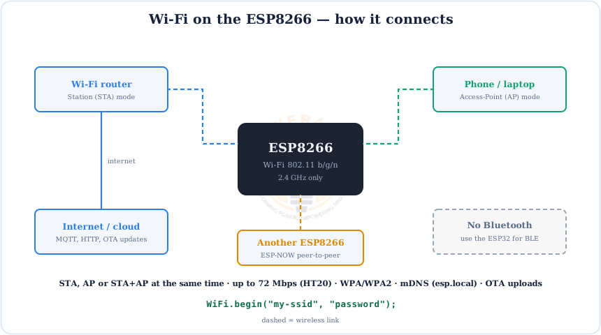
Wi-Fi is what the ESP8266 is for. It can join your router (Station), create its own hotspot (Access Point), do both at once, or talk board-to-board with ESP-NOW. It has no Bluetooth.
// connect to Wi-Fi and print the IP address
#include <ESP8266WiFi.h>
void setup() {
  Serial.begin(115200);
  WiFi.mode(WIFI_STA);
  WiFi.begin("YOUR_SSID", "YOUR_PASSWORD");
  while (WiFi.status() != WL_CONNECTED) { delay(500); Serial.print("."); }
  Serial.println(WiFi.localIP());
}
void loop() {}
Useful extras: mDNS (ESP8266mDNS) lets you open http://mydevice.local, ArduinoOTA uploads new code over Wi-Fi, and WiFiManager shows a setup page so users can enter their Wi-Fi password without re-flashing.
Deep Sleep
With Wi-Fi transmitting, the ESP8266 draws around 170 mA. In deep sleep it needs about 20 µA. To wake itself up, D0 (GPIO16) must be wired to RST.
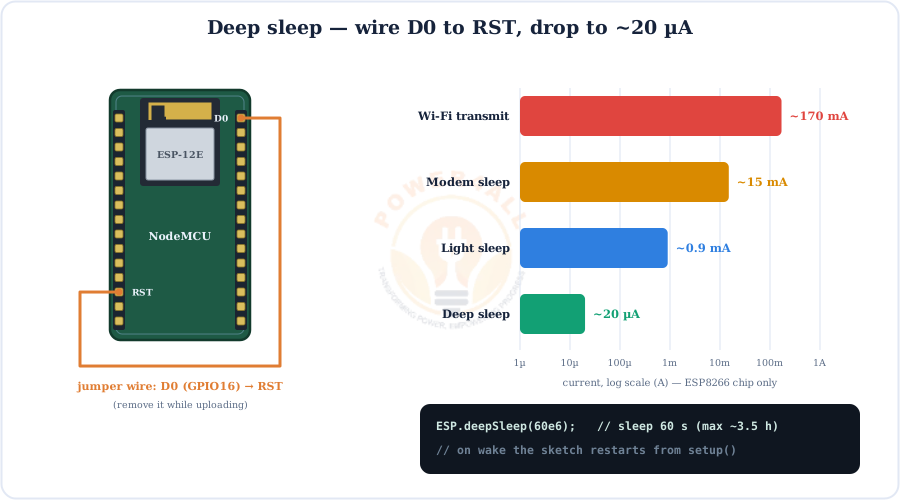
setup() runs again.Real-world battery life
The NodeMCU's regulator, USB chip and LEDs draw several mA even while the ESP8266 sleeps. For months on a battery, use a bare ESP-12 or a low-power board, and keep awake time short (connect, send, sleep). The longest single sleep is about 3.5 hours (ESP.deepSleepMax()).
Programming the NodeMCU & Uploading Code
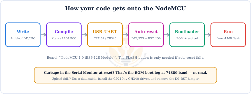
You can program the ESP8266 with the Arduino IDE, PlatformIO, MicroPython or the original NodeMCU Lua firmware. The Arduino IDE is the most popular choice.
Set up the Arduino IDE
- Open File → Preferences and add to Additional boards manager URLs:
https://arduino.esp8266.com/stable/package_esp8266com_index.json - In Boards Manager, install esp8266 by ESP8266 Community.
- Choose Tools → Board → NodeMCU 1.0 (ESP-12E Module) and your Port. No port? Install the CP210x or CH340 driver.
- Click Upload and open the Serial Monitor at 115200 baud.
Upload or boot problems?
Remove the D0–RST jumper and anything on D3/D4/D8, then try a known-good data cable. A burst of garbage characters at reset is the ROM boot log at 74880 baud, which is normal. Repeated resets with “wdt reset” mean a loop that never yields, so add delay(0) or yield().
ESP8266 NodeMCU Code Examples
Short, copy-paste sketches for the Arduino IDE.
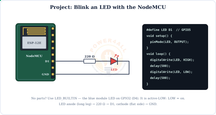
1. Blink an external LED on D1
#define LED D1            // GPIO5
void setup() { pinMode(LED, OUTPUT); }
void loop() {
  digitalWrite(LED, HIGH); delay(500);
  digitalWrite(LED, LOW);  delay(500);
}
2. Blink the built-in LED (active-LOW)
void setup() { pinMode(LED_BUILTIN, OUTPUT); }   // GPIO2 / D4
void loop() {
  digitalWrite(LED_BUILTIN, LOW);  delay(200);    // LOW = ON
  digitalWrite(LED_BUILTIN, HIGH); delay(800);
}
3. Read a button with the internal pull-up
void setup() {
  pinMode(D5, INPUT_PULLUP);          // button between D5 and GND
  pinMode(D1, OUTPUT);
}
void loop() {
  digitalWrite(D1, digitalRead(D5) == LOW);   // LED on while pressed
}
4. Deep sleep for one minute
// wire D0 to RST (remove while uploading)
void setup() {
  Serial.begin(115200);
  Serial.println("Awake! Doing work...");
  ESP.deepSleep(60e6);                // 60 s in microseconds
}
void loop() {}
Beginner NodeMCU Mini-Projects
Small, complete projects that use the NodeMCU's Wi-Fi from day one.
Project 1 — Wi-Fi LED switch (web server)
#include <ESP8266WiFi.h>
#include <ESP8266WebServer.h>
ESP8266WebServer server(80);
void page() {
  server.send(200, "text/html",
    "<h1>NodeMCU</h1><a href='/on'>ON</a> | <a href='/off'>OFF</a>");
}
void setup() {
  pinMode(D1, OUTPUT);
  Serial.begin(115200);
  WiFi.begin("YOUR_SSID", "YOUR_PASSWORD");
  while (WiFi.status() != WL_CONNECTED) delay(500);
  Serial.println(WiFi.localIP());
  server.on("/", page);
  server.on("/on",  [](){ digitalWrite(D1, HIGH); page(); });
  server.on("/off", [](){ digitalWrite(D1, LOW);  page(); });
  server.begin();
}
void loop() { server.handleClient(); }
Project 2 — Potentiometer LED dimmer
void setup() { pinMode(D1, OUTPUT); }
void loop() {
  int raw = analogRead(A0);                  // 0..1023
  analogWrite(D1, map(raw, 0, 1023, 0, 255));  // 0..255 duty
  delay(10);
}
Project 3 — Light meter in your browser
http://IP/light to get the reading as JSON.#include <ESP8266WiFi.h> #include <ESP8266WebServer.h> ESP8266WebServer server(80); void setup() { Serial.begin(115200); WiFi.begin("YOUR_SSID", "YOUR_PASSWORD"); while (WiFi.status() != WL_CONNECTED) delay(500); Serial.println(WiFi.localIP()); server.on("/light", [](){ server.send(200, "application/json", "{\"light\":" + String(analogRead(A0)) + "}"); }); server.begin(); } void loop() { server.handleClient(); }
Project 4 — Sleepy sensor logger
void setup() {
  Serial.begin(115200);
  Serial.printf("Light level: %d\n", analogRead(A0));
  ESP.deepSleep(5 * 60e6);            // 5 minutes
}
void loop() {}
ESP8266 vs ESP32
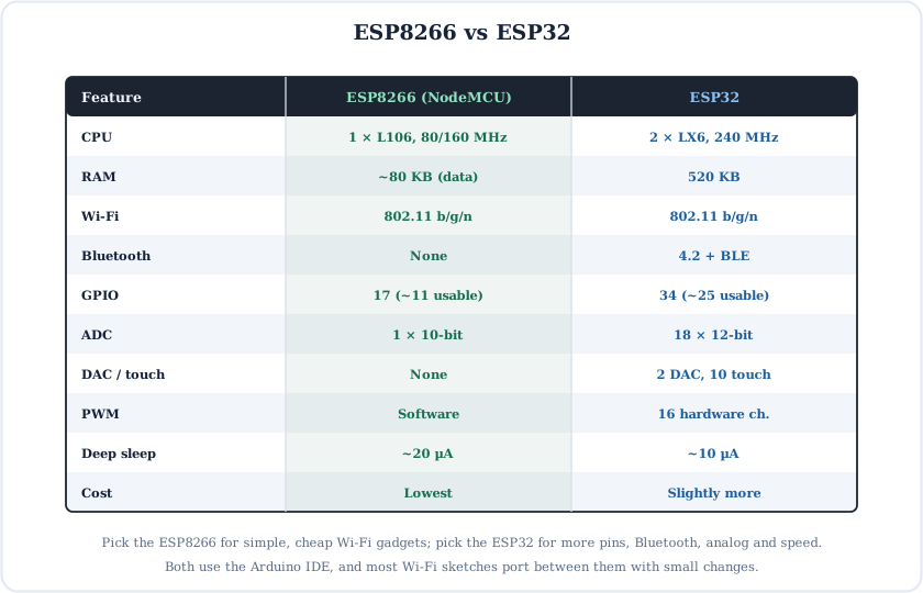
The ESP32 is the ESP8266's bigger brother. Here is how they compare:
NodeMCU vs Arduino Uno: the NodeMCU has a much faster 32-bit CPU, far more flash and built-in Wi-Fi, but uses 3.3 V logic and has only one analog pin. The Arduino Uno is 5 V, has 6 analog inputs and supports classic shields.
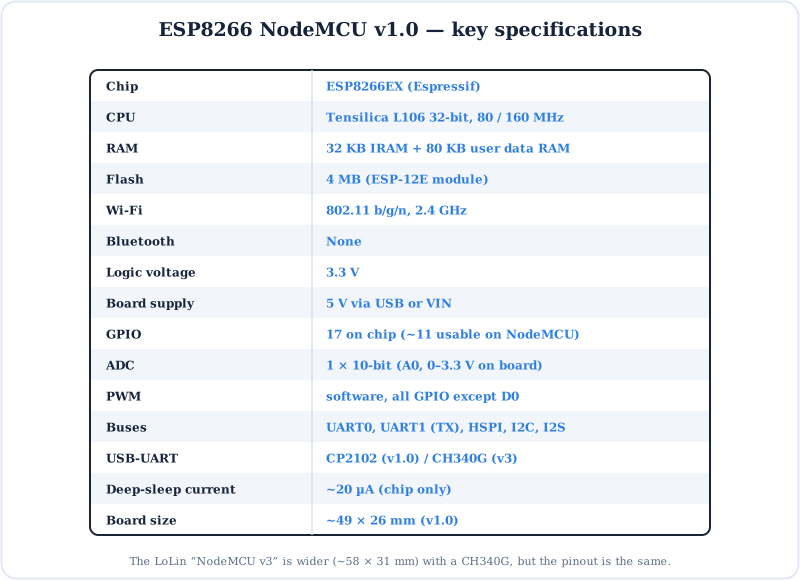
ESP8266 NodeMCU Specifications
Key Terms — Glossary
| Term | Meaning |
|---|---|
| ESP8266EX | Espressif's Wi-Fi SoC with a Tensilica L106 core. |
| NodeMCU | Open-source dev board (and original Lua firmware) built around the ESP-12E. |
| ESP-12E | Shielded module: ESP8266EX + 4 MB flash + crystal + PCB antenna. |
| D-pin | NodeMCU board label (D0–D8), different from the GPIO number. |
| Strapping pin | GPIO0, 2 and 15, read at reset to pick the boot mode. |
| A0 / TOUT | The single 10-bit ADC input. |
| Software PWM | PWM generated by timer interrupts; available on any GPIO except 16. |
| HSPI | The user SPI bus on D5–D8 (the other SPI drives the flash). |
| STA / AP | Station (joins a router) / Access Point (creates a hotspot) Wi-Fi modes. |
| ESP-NOW | Router-free, peer-to-peer packets between Espressif boards. |
| Deep sleep | ~20 µA mode; wake needs GPIO16 (D0) wired to RST. |
| Watchdog (WDT) | Resets the chip if your code blocks too long without yield(). |
| esptool | The tool that writes firmware through the ROM bootloader. |
Frequently Asked Questions
Quick answers to the questions people ask most about the ESP8266 NodeMCU.
What is the ESP8266 NodeMCU?
The ESP8266 is a low-cost Wi-Fi microcontroller from Espressif with a 32-bit Tensilica L106 CPU at 80/160 MHz and built-in 802.11 b/g/n Wi-Fi. The NodeMCU board carries it on an ESP-12E module with 4 MB flash, a USB-to-UART chip and a 3.3 V regulator, so you can program it over USB with the Arduino IDE.
What is the NodeMCU D pin to GPIO mapping?
D0 = GPIO16, D1 = GPIO5, D2 = GPIO4, D3 = GPIO0, D4 = GPIO2, D5 = GPIO14, D6 = GPIO12, D7 = GPIO13, D8 = GPIO15, RX = GPIO3, TX = GPIO1. In Arduino code you can write D1 or 5.
Which NodeMCU pins are safe to use?
D1, D2, D5, D6 and D7 are fully safe. D3, D4 and D8 are boot pins (HIGH, HIGH, LOW at power-up), RX/TX are the USB serial port, D0 has no PWM or interrupts, and SD0–SD3, CMD and CLK belong to the flash and must not be used.
Why won't my ESP8266 boot when something is connected to D3, D4 or D8?
GPIO0 (D3), GPIO2 (D4) and GPIO15 (D8) are read at reset. A normal boot needs GPIO15 LOW and GPIO0/GPIO2 HIGH. A load that pulls D3 or D4 LOW, or D8 HIGH, at power-up selects the wrong boot mode, so your program never starts.
How many analog pins does the NodeMCU have?
Only one. A0 connects to the single 10-bit ADC and returns 0–1023 with analogRead(A0). The NodeMCU's 220k/100k divider lets A0 accept 0–3.3 V; the bare chip only accepts 0–1 V.
Is the ESP8266 5 V tolerant?
The ESP8266 is a 3.3 V chip and Espressif doesn't rate its GPIO as 5 V tolerant, so level-shift 5 V signals. The NodeMCU board can be powered from 5 V on USB or VIN because its AMS1117 regulator makes 3.3 V.
How does deep sleep work on the NodeMCU?
Call ESP.deepSleep(microseconds) and the chip drops to about 20 µA. Wire D0 (GPIO16) to RST: the RTC pulses GPIO16 LOW when the time is up, which resets the chip, and setup() runs again. Remove the wire while uploading.
Should I use the ESP8266 or the ESP32?
Use the ESP8266 for simple, low-cost Wi-Fi projects such as smart switches and sensor loggers. Choose the ESP32 if you need Bluetooth, more GPIO, several analog inputs, a DAC, touch pins, hardware PWM or more speed and memory.
Conclusion & Key Takeaways
The ESP8266 NodeMCU is the cheapest, simplest way to put a project on Wi-Fi. Learn the D-pin mapping, respect the three boot pins and remember it's a 3.3 V chip, and it will serve you well.
Wi-Fi SoC
L106 at 80/160 MHz.
D ≠ GPIO
D1 = GPIO5, D2 = GPIO4.
Boot pins
D3/D4 HIGH, D8 LOW.
One ADC
A0: 0–3.3 V → 0–1023.
3.3 V logic
Level-shift 5 V parts.
Deep sleep
~20 µA, D0 → RST.