What is Power Factor (cos φ)?
The complete guide to power factor — how much of the power you are supplied actually does useful work. From PF = cos φ = P/S and the power triangle to leading vs lagging power factor, why a low power factor costs money, and how capacitors correct it.
Complete Learning Path — Power Factor
From what power factor is and the power triangle, to leading vs lagging PF, why it matters, correction with capacitors and worked examples
What is Power Factor?
Power factor (PF) is the ratio of real power to apparent power in an AC circuit — a number that tells you how much of the power drawn from the supply is actually doing useful work. It equals the cosine of the phase angle between voltage and current, so it is written PF = cos φ.
Power factor is a pure ratio, so it has no unit and always lies between 0 and 1 (or 0% to 100%). A power factor of 1 (unity) means every watt supplied does useful work; a low power factor means a lot of current is flowing back and forth without delivering net energy.
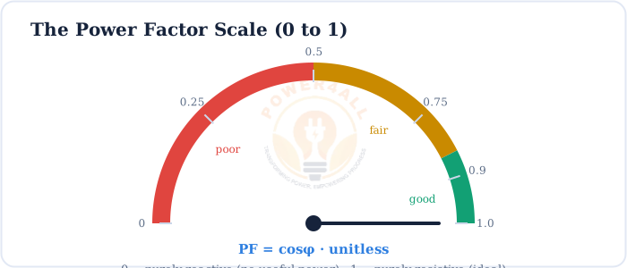
Real power vs apparent power
Real power (P, watts) is the power that does work — heat, light, torque. Apparent power (S, volt-amperes) is simply voltage × current, what the supply and cables must actually carry. Power factor is the fraction of that apparent power which becomes real power.
Power Factor & the Power Triangle
In AC circuits power comes in three flavours — real, reactive and apparent — and they combine like the sides of a right triangle. Power factor is the cosine of the angle at the base.
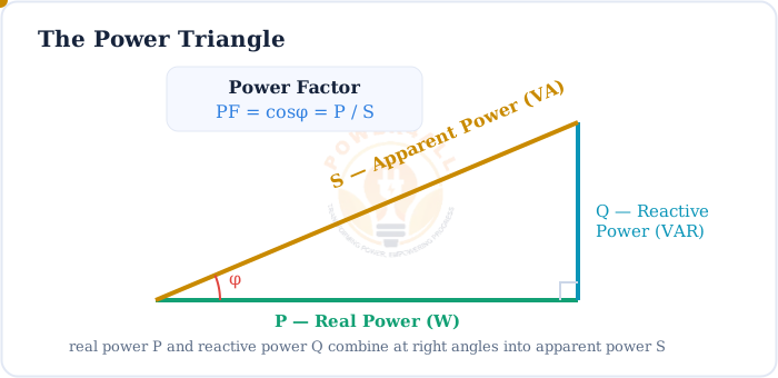
Real Power (P)
The working power that does the job. Unit: watt (W) / kW. P = VI cosφ
Reactive Power (Q)
Power that sloshes to and from inductors/capacitors. Unit: VAR. Q = VI sinφ
Apparent Power (S)
Total power the supply carries. Unit: VA / kVA. S = VI = √(P²+Q²)
S² = P² + Q² · PF = cosφ = P / S
The power triangle: apparent power is the hypotenuse; power factor is the base over the hypotenuse
kW, kVAR and kVA
The same triangle in engineering units: kVA² = kW² + kVAR², and power factor = kW / kVA. That is why a 100 kVA supply at PF 0.8 delivers only 80 kW of useful power.
Power Factor = cos φ (the Phase View)
Power factor comes from the phase shift between the voltage and current waves. The bigger the shift φ, the smaller cos φ, and the poorer the power factor.
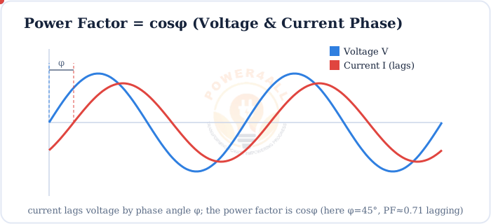
PF = cosφ = P / (V × I)
φ is the phase angle between the voltage and current; when they are in phase, φ = 0 and PF = 1
Displacement vs true power factor
For clean sine waves, PF = cos φ (called displacement power factor). With non-linear loads (drives, LED drivers) current harmonics lower the true power factor even further, so PF ≤ cos φ.
Leading vs Lagging vs Unity Power Factor
Whether the power factor is lagging or leading depends on the type of load — inductive or capacitive. A purely resistive load gives unity power factor.
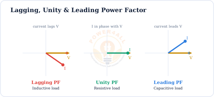
| Power Factor | Load type | Current vs voltage | Examples |
|---|---|---|---|
| Lagging | Inductive | Current lags voltage | Motors, transformers, fluorescent ballasts |
| Unity (1.0) | Resistive | In phase (φ = 0) | Heaters, incandescent lamps, kettles |
| Leading | Capacitive | Current leads voltage | Capacitor banks, lightly loaded cables |
Most real loads are lagging
Industry runs mostly on motors and transformers, which are inductive, so plant power factor is usually lagging. That is exactly why correction uses capacitors, which pull the power factor back up.
Why Power Factor Matters
A poor power factor doesn't change the useful work done, but it forces more current through the whole system — and that costs real money.
Higher losses
More current means more I²R heating in cables and windings.
Voltage drop
Extra current causes bigger voltage drops along feeders.
Wasted capacity
Transformers and cables are sized in kVA — low PF eats their headroom.
Utility penalties
Many tariffs surcharge industrial users below ~0.9 PF.
The current penalty of low PF
A load needs P = 50 kW at 415 V. Compare the current at two power factors:
At PF = 1.0: S = 50 kVA → current is minimum.
At PF = 0.5: S = P/PF = 100 kVA — double the current for the very same 50 kW of work, so four times the I²R losses.
Power Factor Correction
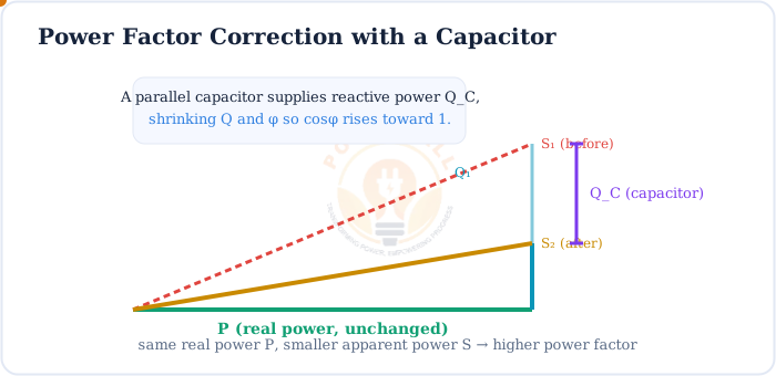
Because most loads are inductive (lagging), we add capacitors in parallel. They supply leading reactive power that cancels the inductive reactive power, shrinking Q and the angle φ — so the power factor climbs toward 1.
QC = P × (tanφ₁ − tanφ₂)
Capacitor reactive power (kVAR) needed to move the power factor from cosφ₁ up to the target cosφ₂
Worked example — sizing a capacitor
A 40 kW load runs at PF = 0.7 lagging. Raise it to 0.95.
φ₁ = cos⁻¹(0.7) = 45.6° → tanφ₁ = 1.02
φ₂ = cos⁻¹(0.95) = 18.2° → tanφ₂ = 0.329
QC = 40 × (1.02 − 0.329) ≈ 27.6 kVAR of capacitors.
Do it instantly with the Power Factor Correction Capacitor Calculator, or check any load with the Power Factor Calculator.
How to Calculate Power Factor
You can find power factor from powers, from voltage & current, or from the phase angle — whichever you have measured.
PF = P / S = P / (V × I)
Single-phase: real power divided by the product of RMS voltage and current
PF = P / (√3 × VL × IL)
Three-phase, using line voltage and line current
Example 1 — from powers
A load draws S = 10 kVA and delivers P = 8 kW. Then PF = 8/10 = 0.8 lagging, and the phase angle is cos⁻¹(0.8) = 37°.
Example 2 — from V, I and P
A single-phase motor: V = 230 V, I = 6 A, wattmeter reads P = 1104 W.
S = 230 × 6 = 1380 VA, so PF = 1104 / 1380 = 0.8.
Example 3 — from the angle
If the current lags the voltage by φ = 25.8°, then PF = cos(25.8°) = 0.9 lagging.
Where Power Factor Matters
Power factor is a headline number in every industrial and utility power system.
Industry & plants
Motor-heavy factories install capacitor banks to avoid PF penalties and free up transformer capacity.
Utilities & grid
Reactive power management keeps voltages in range and cuts transmission losses.
Power electronics
Active PFC front-ends in PC supplies and LED drivers keep input PF near 1.
Motors & drives
Lightly loaded motors have poor PF; correct at the load or at the busbar.
Key Terms at a Glance
The essential power-factor vocabulary students and engineers search for.
Power factor (PF)
cosφ = P/S; unitless, 0 to 1.
Real power (P)
Working power in watts; VI cosφ.
Reactive power (Q)
Stored/returned power in VAR; VI sinφ.
Apparent power (S)
Total power in VA; VI.
Phase angle (φ)
Angle between V and I; PF = cosφ.
PF correction
Adding capacitors to raise PF toward 1.
Frequently Asked Questions
Quick, expert answers to the questions people ask most about power factor.
What is power factor in simple words?
Power factor is how much of the electricity you draw actually does useful work. It is the ratio of real power (watts) to apparent power (volt-amperes), equal to cos φ, and ranges from 0 to 1. Closer to 1 is better.
What is the formula for power factor?
PF = P / S = cosφ. For a single-phase load, PF = P / (V × I); for three-phase, PF = P / (√3 × VL × IL).
Is power factor unitless?
Yes — it is watts divided by volt-amperes, so the units cancel. It is written as a decimal from 0 to 1 (or a percentage), usually tagged “leading” or “lagging”.
What is the difference between leading and lagging power factor?
Lagging PF: current lags voltage (inductive loads like motors). Leading PF: current leads voltage (capacitive loads). A resistive load gives unity power factor with current and voltage in phase.
Why is a low power factor bad?
Low PF means large reactive power, so more current flows for the same useful power. That raises I²R losses, causes voltage drop, wastes cable and transformer capacity, and often triggers a utility penalty.
How is power factor corrected?
Capacitors are connected in parallel with inductive loads. They supply leading reactive power that cancels part of the lagging reactive power, shrinking Q and φ and raising PF toward 1.
What is a good power factor?
0.95–1.0 is good. Many utilities target about 0.9–0.95 for industrial supplies and penalise anything below. Unity (1.0) is ideal, where apparent power equals real power.
What does a power factor of 0.8 lagging mean?
cos φ = 0.8 with current lagging voltage, so the load is inductive. Only 80% of the apparent power does useful work, the phase angle is about 37°, and reactive power is 0.6 × the apparent power.
Conclusion & Key Takeaways
Power factor is the single number that tells you how efficiently an AC circuit turns supplied power into useful work — the cosine of the phase angle, PF = cos φ = P/S.
PF = cosφ = P/S
Real over apparent power.
Unitless, 0–1
1 is ideal (unity).
Power triangle
S² = P² + Q².
Leading or lagging
Capacitive vs inductive.
Low PF is costly
More current, more loss, penalties.
Correct with capacitors
Cancel reactive power.