STM32F401 Black Pill
The Blue Pill's faster, tidier successor. The Black Pill is built on the STM32F401CCU6 — an ARM Cortex-M4 with a hardware FPU at 84 MHz, 256 KB flash, 64 KB SRAM, a 12-bit ADC and native USB-C. Best of all, its built-in USB DFU bootloader means you can flash it with no ST-Link. This guide covers the full board anatomy, a complete pinout with every port pin explained, 3.3 V logic & 5 V-tolerance, power, the buses, USB DFU / SWD programming, the BOOT0 button, a Black Pill vs Blue Pill vs Uno comparison, and code and mini-projects.
Complete Learning Path — STM32F401 Black Pill
From board anatomy and the Cortex-M4 STM32F401CCU6, to a full port pinout with every pin detailed, 3.3 V logic, power, digital & analog I/O, PWM, the buses, USB-C DFU / SWD programming, the BOOT0 button, Black Pill vs Blue Pill, code and mini-projects
What is the STM32F401 Black Pill?
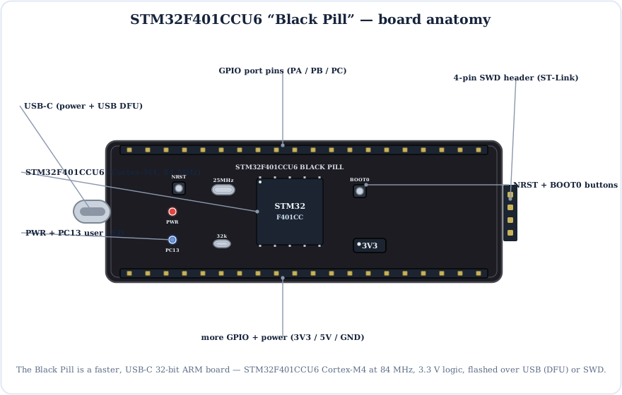
The STM32F401 Black Pill is a tiny, low-cost development board built around the STM32F401CCU6 — a 32-bit ARM Cortex-M4 with a hardware floating-point unit (FPU). It is the modern answer to the Blue Pill: faster, more memory, a reliable USB-C port, and a factory USB bootloader so you can flash it with no programmer.
Made popular by WeAct, it drops straight into a breadboard and works with the Arduino IDE (STM32duino core), STM32CubeIDE or PlatformIO.
The Brain: STM32F401CCU6
At the centre sits the STM32F401CCU6 — a 32-bit ARM Cortex-M4 clocked to 84 MHz (multiplied by an internal PLL from the 25 MHz crystal). The Cortex-M4 adds a hardware FPU and DSP instructions, so floating-point maths runs far faster than on the Blue Pill's M3.
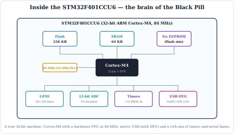
- Flash (256 KB) — four times the Blue Pill; plenty of room for big sketches.
- SRAM (64 KB) — working memory for variables and buffers.
- No EEPROM — there is no dedicated EEPROM; libraries emulate it in flash.
- Cortex-M4 + FPU — hardware floating point and DSP, great for audio, sensors and control maths.
Full STM32F401 Black Pill Pinout
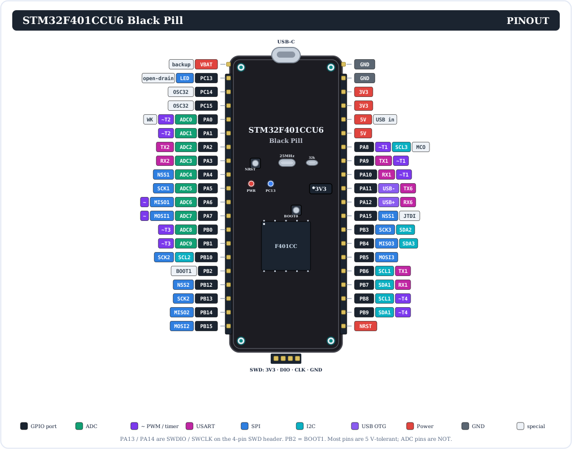
Here is the complete pinout. Like every STM32, pins are named by port and number — PA0…PA15, PB0…PB15 and PC13…PC15 — and each has several alternate functions.
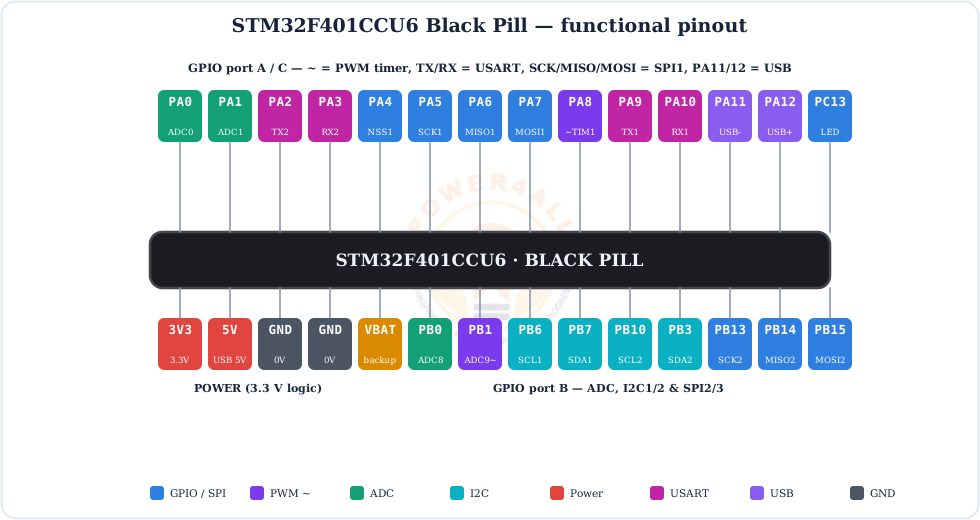
Prefer a simpler view? This colour-coded map groups the pins by function:
Every Pin Explained
Let's go through each group of pins. On the STM32 a single pin often has many roles — you pick one in software.
GPIO pins (PA / PB / PC)
30+ general-purpose pins that read or write HIGH (3.3 V) or LOW (0 V) with pinMode(), digitalWrite() and digitalRead(). Each handles about 20 mA (25 mA max), with configurable built-in pull-ups and pull-downs.
PC13
The on-board user LED — and it is active-low (LOW = on).
PB6 / PB7
I2C1 (SCL / SDA). Second/third buses: I2C2 & I2C3.
PA9 / PA10
USART1 (TX / RX) — the usual serial console pins.
Timer pins (~)
Many PWM channels across TIM1–TIM5, TIM9–TIM11.
PA11 / PA12
Native USB OTG D− / D+ (the USB-C data lines).
Analog input pins (10 channels)
One 12-bit ADC with 10 external channels, each reading 0–3.3 V as 0–4095:
- PA0–PA7 (ADC channels 0–7) and PB0, PB1 (channels 8, 9).
- Read them with
analogRead(PA0); callanalogReadResolution(12)for the full range. - Warning: the ADC pins are not 5 V-tolerant — keep them at 3.3 V max.
The buses (and their pins)
| Bus | Bus 1 pins | More buses |
|---|---|---|
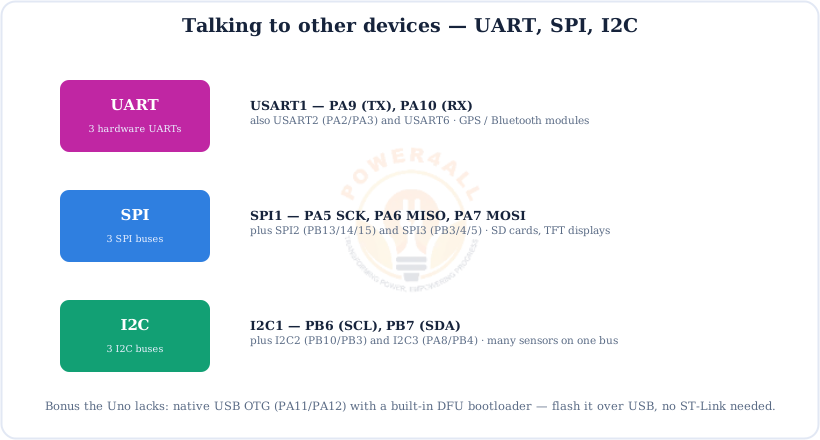
| UART | USART1: PA9 (TX) / PA10 (RX) | USART2 (PA2/PA3), USART6 |
| SPI | SPI1: PA5 SCK, PA6 MISO, PA7 MOSI | SPI2 (PB13/14/15), SPI3 (PB3/4/5) |
| I2C | I2C1: PB6 (SCL) / PB7 (SDA) | I2C2, I2C3 |
| USB | USB OTG: PA11 (D−) / PA12 (D+) | on the USB-C connector |
Power & programming pins
5V (USB input / output), 3.3V (regulated out), GND, VBAT (backup domain), NRST, plus the 4-pin SWD header (3V3, SWDIO = PA13, SWCLK = PA14, GND). There is no barrel jack.
No CAN on the F401
Unlike the Blue Pill's STM32F103, the STM32F401 has no CAN bus. If your project needs CAN, pick the Blue Pill (or an F405/F446 board) instead. Everything else here is an upgrade.
3.3 V Logic — and the 5 V Trap
Like all STM32 boards, the Black Pill runs at 3.3 V. Most digital pins are 5 V-tolerant as inputs, but the analog pins are not — getting this wrong can damage the chip.
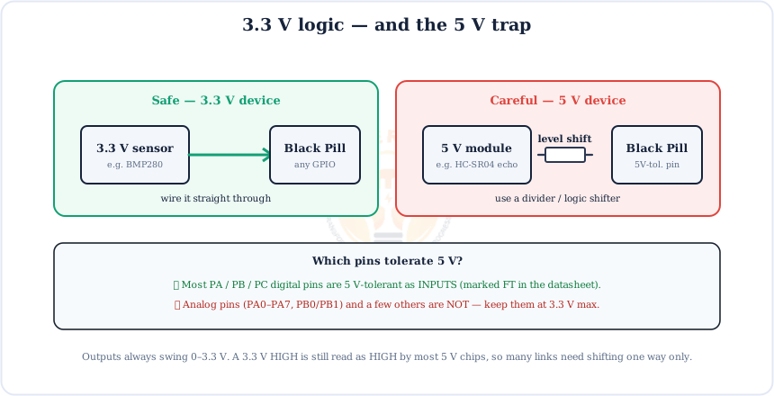
- 5 V-tolerant (FT) pins — most PA/PB/PC digital pins can safely read a 5 V input.
- NOT 5 V-tolerant — the analog pins PA0–PA7, PB0 and PB1, plus a few others.
- Outputs always swing 0–3.3 V. A 3.3 V HIGH is still read as HIGH by most 5 V chips.
Powering the Black Pill
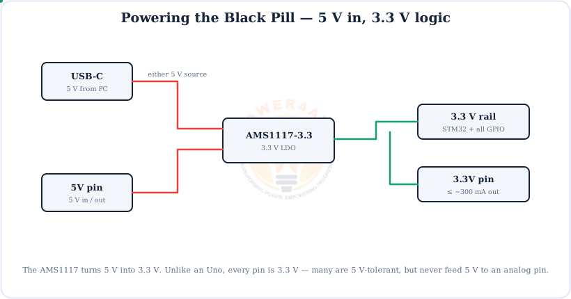
Power it from USB-C (5 V) or feed 5 V into the 5V pin. An on-board AMS1117 regulator makes the 3.3 V the chip and every GPIO run on.
Feeding 3.3 V directly
If you already have a clean 3.3 V supply, you can power the board through the 3.3V pin and skip the on-board regulator. Don't power both USB and an external 3.3 V at the same time.
Digital I/O
Output a HIGH/LOW to drive an LED or relay, or read a HIGH/LOW input from a button or sensor — all at 3.3 V.
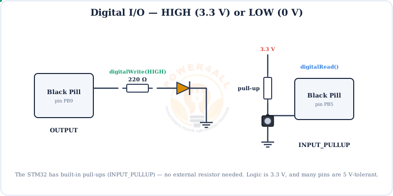
INPUT_PULLUP — no external resistor needed.// digital output + input (STM32, 3.3 V) void setup() { pinMode(PB9, OUTPUT); // LED pin pinMode(PB5, INPUT_PULLUP); // button to GND } void loop() { digitalWrite(PB9, !digitalRead(PB5)); // LED follows the button }
PWM Output (~)
PWM fakes an analog voltage by switching a pin on and off fast. The STM32F401 has powerful timers giving many PWM channels across the PA/PB pins.
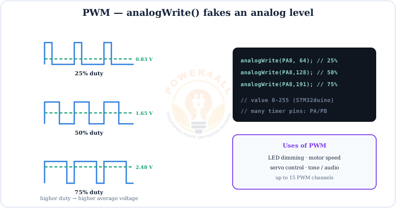
analogWrite(pin, 0–255) on any timer pin such as PA8.// fade an LED on a PWM/timer pin (PA8) void setup() { pinMode(PA8, OUTPUT); } void loop() { for (int v = 0; v <= 255; v++) { analogWrite(PA8, v); delay(5); } for (int v = 255; v >= 0; v--) { analogWrite(PA8, v); delay(5); } }
Analog Input (ADC)
The Black Pill's 12-bit ADC is far finer than an Uno's 10-bit one. Each reading turns 0–3.3 V into 0–4095 — about 0.8 mV per step.
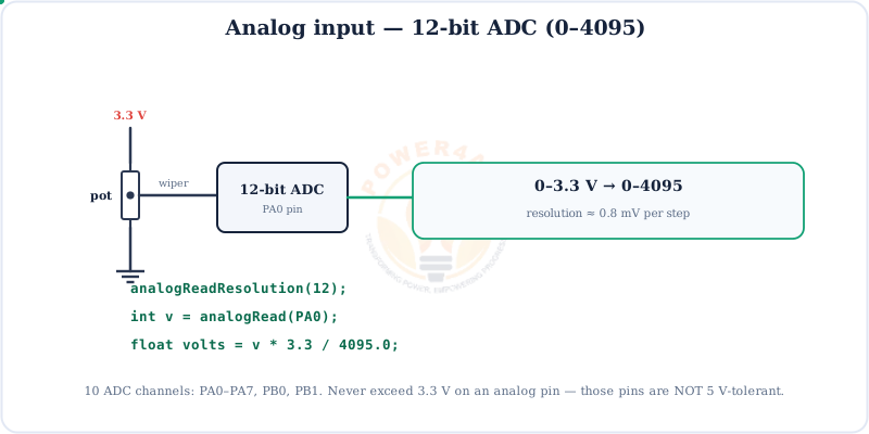
v * 3.3 / 4095.0. Keep analog pins at 3.3 V max.// read a 12-bit analog input on PA0 void setup() { Serial.begin(115200); analogReadResolution(12); // full 0..4095 range } void loop() { int raw = analogRead(PA0); // 0..4095 float volts = raw * 3.3 / 4095.0; Serial.println(volts); delay(200); }
UART, SPI & I2C
The STM32F401 is generous with buses: three UARTs, three SPI and three I2C — plus native USB OTG. (It has no CAN, unlike the Blue Pill.)
How Code Gets onto the Black Pill
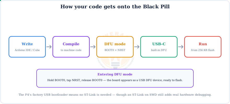
The Black Pill's best trick: a built-in USB DFU bootloader, so you can flash it straight over USB-C with no ST-Link.
Arduino IDE setup
Install the “STM32 MCU based boards” core, pick Generic STM32F4 → Black Pill F401CC, and set the upload method to STM32CubeProgrammer (DFU). Put the board in DFU mode first (see below). Prefer debugging? Use an ST-Link on the SWD header instead.
The BOOT0 Button & DFU Mode
Where the Blue Pill uses jumpers, the Black Pill has a BOOT0 button. Use it with NRST to drop into USB DFU mode.
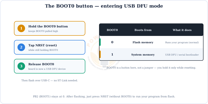
After flashing, just press NRST on its own (without BOOT0) to run your program. You only hold BOOT0 when you want to upload.
Black Pill vs Blue Pill vs Arduino Uno
Should you get a Black Pill or a Blue Pill? The Black Pill is faster and easier to flash; the Blue Pill keeps CAN and the ST-Link workflow.
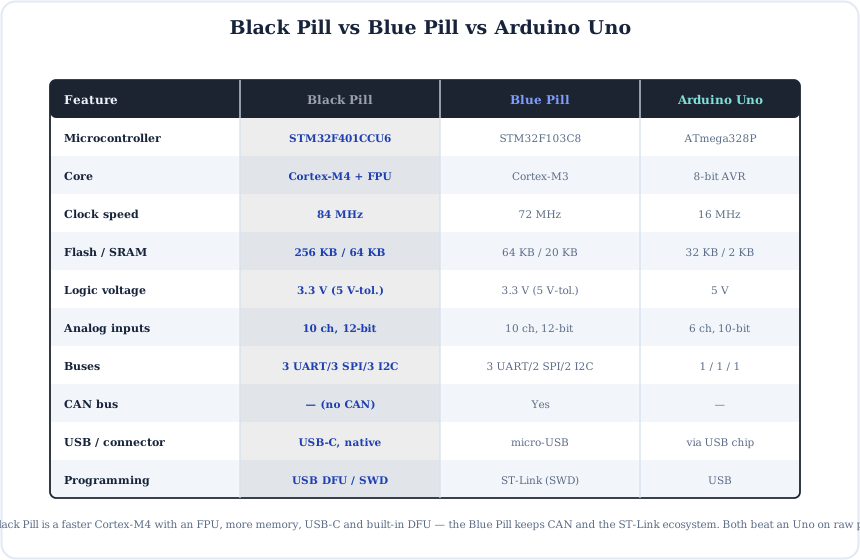
Choose the Black Pill for the most power, the FPU, USB-C and no-programmer flashing; choose the Blue Pill if you need CAN or already use ST-Link; choose the Uno/Nano for 5 V shields and the biggest beginner ecosystem. For a 32-bit ARM board that uploads over USB like an Arduino, see the Arduino Due.
Code Examples
The everyday building blocks, written for the STM32duino core.
1. Blink the on-board PC13 LED (active-low)
void setup() { pinMode(PC13, OUTPUT); }
void loop() {
  digitalWrite(PC13, LOW);  delay(1000);   // LED on
  digitalWrite(PC13, HIGH); delay(1000);   // LED off
}
2. Fast floating-point maths (the FPU at work)
void setup() { Serial.begin(115200); }
void loop() {
  float sum = 0;
  for (int i = 1; i <= 1000; i++) sum += sqrtf(i) * sinf(i);  // FPU-accelerated
  Serial.println(sum, 4);
  delay(500);
}
3. Talk to a module on USART1 (PA9 / PA10)
// Serial1 is USART1 on PA9 (TX) / PA10 (RX)
void setup() {
  Serial.begin(115200);      // USB to PC
  Serial1.begin(9600);       // module on PA9/PA10
}
void loop() {
  if (Serial1.available()) Serial.write(Serial1.read());
}
Beginner Mini-Projects
Four small builds that show off the Black Pill's strengths.
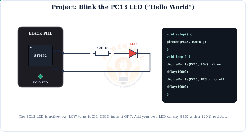
Project 1 — Blink the PC13 LED
void setup() { pinMode(PC13, OUTPUT); }
void loop() {
  digitalWrite(PC13, LOW);  delay(500);
  digitalWrite(PC13, HIGH); delay(500);
}
Project 2 — Button with a built-in pull-up
void setup() {
  pinMode(PC13, OUTPUT);
  pinMode(PB5, INPUT_PULLUP);
}
void loop() {
  if (digitalRead(PB5) == LOW) digitalWrite(PC13, LOW);   // pressed = LED on
  else                          digitalWrite(PC13, HIGH);
}
Project 3 — 12-bit potentiometer meter
void setup() {
  Serial.begin(115200);
  analogReadResolution(12);
}
void loop() {
  int raw = analogRead(PA0);
  Serial.println(raw * 3.3 / 4095.0, 3);   // volts
  delay(100);
}
Project 4 — I2C scanner on PB6/PB7
Wire library.#include <Wire.h> void setup() { Serial.begin(115200); Wire.begin(); // I2C1: SCL=PB6, SDA=PB7 } void loop() { for (byte a = 1; a < 127; a++) { Wire.beginTransmission(a); if (Wire.endTransmission() == 0) { Serial.print("found 0x"); Serial.println(a, HEX); } } delay(2000); }
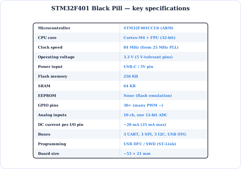
Specifications
The STM32F401 Black Pill at a glance.
Key Terms — Glossary
| Term | Meaning |
|---|---|
| STM32F401CCU6 | The Black Pill's 32-bit ARM Cortex-M4 microcontroller. |
| Cortex-M4 | ARM's 32-bit core with a hardware FPU, running at 84 MHz here. |
| FPU | Floating-point unit — does decimal maths in hardware, fast. |
| DFU | Device Firmware Upgrade — flash over USB with no programmer. |
| BOOT0 button | Held with NRST to enter DFU / the system bootloader. |
| SWD | Serial Wire Debug — the 2-wire program/debug interface. |
| Port pin (PAx) | STM32 naming: port letter + number, e.g. PA5, PB7, PC13. |
| 5 V-tolerant (FT) | A pin that can safely accept a 5 V input despite 3.3 V logic. |
| PC13 LED | The on-board user LED — active-low (LOW = on). |
| STM32duino | The Arduino core that programs STM32 boards with Arduino code. |
Frequently Asked Questions
Quick answers to the questions people ask most about the STM32F401 Black Pill.
What is the STM32F401 Black Pill?
A tiny, low-cost board built on the STM32F401CCU6, a 32-bit ARM Cortex-M4 with a hardware FPU at 84 MHz, with 256 KB flash and 64 KB SRAM. It has 30+ GPIO, a 12-bit ADC, many PWM timers, three UARTs, three SPI, three I2C and native USB on USB-C — and it flashes over USB with no ST-Link.
Black Pill vs Blue Pill — what's different?
The Black Pill (F401) is a faster Cortex-M4 with an FPU at 84 MHz, 256 KB/64 KB memory, USB-C and built-in USB DFU. The Blue Pill (F103) is a Cortex-M3 at 72 MHz with 64 KB/20 KB, micro-USB, a CAN bus, and usually needs an ST-Link. The F401 has no CAN.
How do I program it?
Easiest is USB DFU: hold BOOT0, tap NRST, release, then upload over USB-C with the STM32CubeProgrammer (DFU) method — no ST-Link. You can also use an ST-Link on the SWD header (adds debugging) or upload over serial. Use the STM32duino core to write Arduino sketches.
Is it 5 V-tolerant?
It runs at 3.3 V. Most digital PA/PB/PC pins are 5 V-tolerant as inputs (marked FT), so they can read 5 V signals. But the analog pins (PA0–PA7, PB0, PB1) are NOT 5 V-tolerant, and outputs only swing 0–3.3 V. Never put 5 V on an analog pin.
How do I enter DFU mode?
Hold the BOOT0 button, briefly tap NRST while still holding BOOT0, then release. The board appears to the PC as a USB DFU device, ready to flash over USB-C. After flashing, press NRST on its own to run your program from flash.
Does the F401 have CAN?
No. The STM32F401 has no CAN controller. If you need CAN, choose the Blue Pill (STM32F103) or a higher STM32F4 such as the F405/F446. Everything else on the Black Pill is a step up from the Blue Pill.
Which pin is the on-board LED?
The user LED is on PC13 and is active-low: digitalWrite(PC13, LOW) turns it on and HIGH turns it off. A separate red PWR LED lights whenever the board is powered.
Where are UART, SPI and I2C?
USART1 on PA9/PA10 (plus USART2 PA2/PA3 and USART6); SPI1 on PA5/PA6/PA7 (plus SPI2 PB13/14/15 and SPI3 PB3/4/5); I2C1 on PB6/PB7 (plus I2C2 and I2C3). Native USB OTG is on PA11/PA12 (the USB-C data lines).
Conclusion & Key Takeaways
The STM32F401 Black Pill is the Blue Pill done better — faster Cortex-M4 with an FPU, more memory, USB-C, and flashing with no programmer.
Cortex-M4 + FPU
32-bit, 84 MHz.
256 / 64 KB
Flash / SRAM.
USB-C DFU
No ST-Link needed.
3.3 V logic
Many 5 V-tolerant pins.
12-bit ADC
3 UART/SPI/I2C.
PC13 LED
Active-low.