Maximum Power Transfer Theorem
A source delivers the most power to a load only when the load resistance equals the source resistance — RL = RS. Learn the tell-tale power curve, the Pmax = VTH²/4RS formula, a clean derivation, why the efficiency is only 50%, AC conjugate matching, and where it is used in the real world.
Complete Learning Path — Maximum Power Transfer
From the source-load model and the power curve, to the matching condition, derivation, the Pmax formula, efficiency, AC conjugate matching and real applications
What is the Maximum Power Transfer Theorem?
The Maximum Power Transfer Theorem states that a source with a fixed internal resistance delivers the greatest possible power to a load when the load resistance is made equal to the source (Thévenin) resistance — that is, when RL = RS.
Any real source — a battery, an amplifier output, an antenna, a sensor — can be reduced to a Thévenin equivalent: an ideal voltage VTH in series with a resistance RS. The theorem answers a very practical question: for that fixed source, what load draws the most watts? The surprising answer is not "the smallest load" or "the largest load", but the one that matches the source.
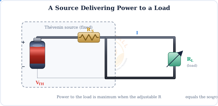
One fixed source, one adjustable load
The theorem assumes the source (VTH and RS) is fixed and only the load is varied. It tells you the best load for a given source — not how to redesign the source itself.
The Source & Load Model
Everything starts with the Thévenin model. Whatever the real network, we replace it with a single voltage source VTH behind a single series resistance RS, feeding the load RL.
The same current flows through both resistances in this series loop:
I = VTH / (RS + RL)
Loop current — it depends on the total resistance in the circuit
The power actually delivered to the load is the current squared times the load resistance, PL = I²RL. Because the current falls as RL grows while the RL factor rises, these two effects fight each other — and their tug-of-war produces a single, clear peak.
Why a peak must exist
Tiny RL: big current, but almost no resistance to develop power across → low P. Huge RL: plenty of resistance, but the current is choked → low P. Somewhere in between lies the sweet spot.
The Power-vs-Load Curve
Plot the load power against the load resistance and the whole idea becomes obvious: the curve rises to a single maximum exactly at RL = RS, then tails off.
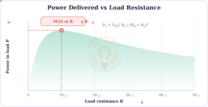
The curve is gently peaked: near the match, small changes in RL barely change the power, which is why real matching does not have to be perfect to work well. Far from the match, though, the power drops away sharply.
The Matching Condition: RL = RS
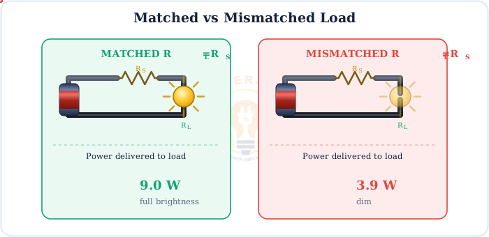
At the peak the load "matches" the source. A simple picture: a lamp as the load glows brightest exactly when its resistance equals the source resistance.
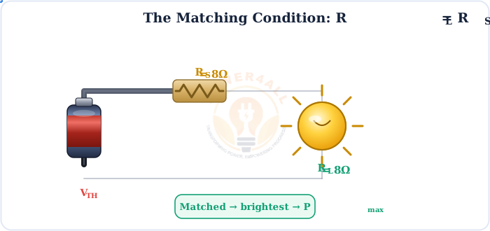
RL = RS
The condition for maximum power transfer in a DC (purely resistive) circuit
Derivation & Proof
The condition RL = RS is not a guess — it drops straight out of maximising the load-power expression with a little calculus.
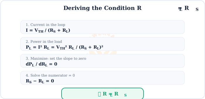
See the full step-by-step working
1. Loop current: I = VTH / (RS + RL)
2. Load power: PL = I²RL = VTH²RL / (RS + RL)²
3. Differentiate and set to zero: dPL/dRL = 0. Using the quotient rule, the numerator becomes VTH²[(RS + RL)² − RL·2(RS + RL)] = 0.
4. Cancel (RS + RL) and simplify: (RS + RL) − 2RL = 0 → RS − RL = 0.
5. Therefore RL = RS. (The second derivative is negative here, confirming it is a maximum, not a minimum.)
The Maximum Power Formula & a Worked Example
Put RL = RS back into the power expression and the maximum power simplifies beautifully:
Pmax = VTH² / 4RS
Maximum power delivered to the load when RL = RS
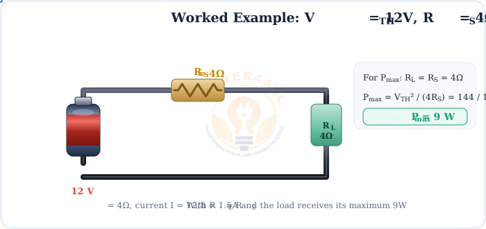
Worked example
A source has VTH = 12 V and RS = 4Ω. Find the load for maximum power and that power.
Match: RL = RS = 4Ω.
Current: I = 12 / (4 + 4) = 1.5 A.
Power: Pmax = VTH²/4RS = 144/16 = 9 W (and you can check P = I²RL = 1.5²×4 = 9 W).
Second example
A sensor modelled as VTH = 10 V, RS = 50Ω. Maximum power reaches the meter when RL = 50Ω, giving Pmax = 10²/(4×50) = 100/200 = 0.5 W.
Efficiency at Maximum Power = 50%
Here is the twist that trips people up: transferring maximum power is not the same as being efficient. At the match, exactly half the total power is wasted heating RS.
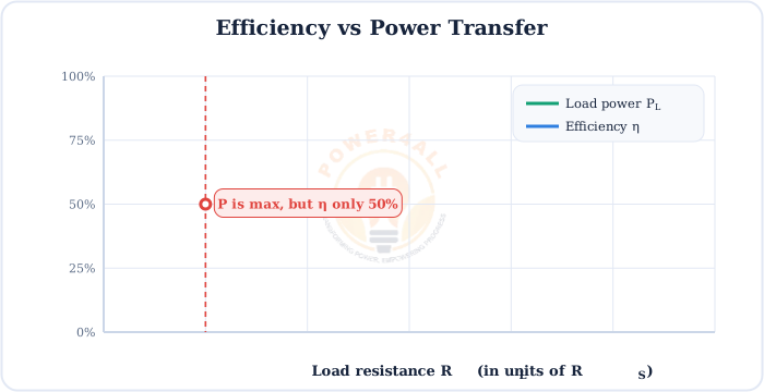
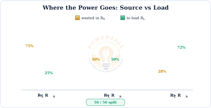
Power vs efficiency — two different goals
Signal circuits (antennas, audio, sensors) want maximum power and accept 50% efficiency. Power systems (the grid, motors) want maximum efficiency, so they deliberately keep RL >> RS — less power to any single load, but very little wasted.
AC Circuits: Conjugate Matching
In AC circuits the source and load have impedance, not just resistance. For maximum power the load must be the complex conjugate of the source impedance: ZL = ZS*.
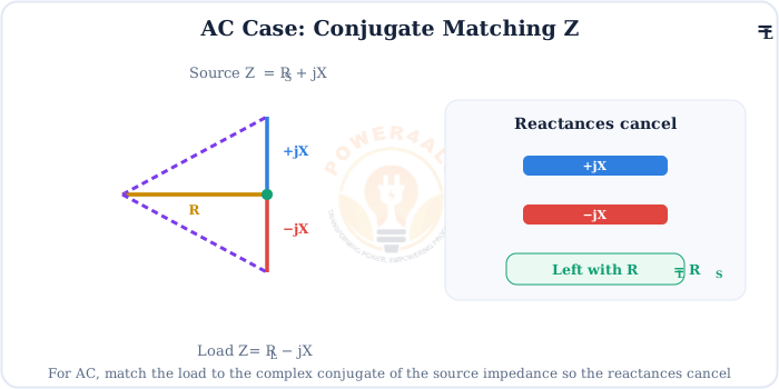
ZL = ZS* → RL = RS, XL = −XS
Conjugate match: equal resistances and equal-but-opposite reactances
Cancelling the reactance makes the circuit look purely resistive at the operating frequency, so the problem reduces to the familiar RL = RS case. This is exactly what a matching network (or an L-C tuned circuit) is built to do.
Applications — Where Matching Matters
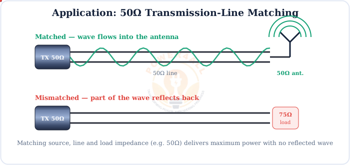
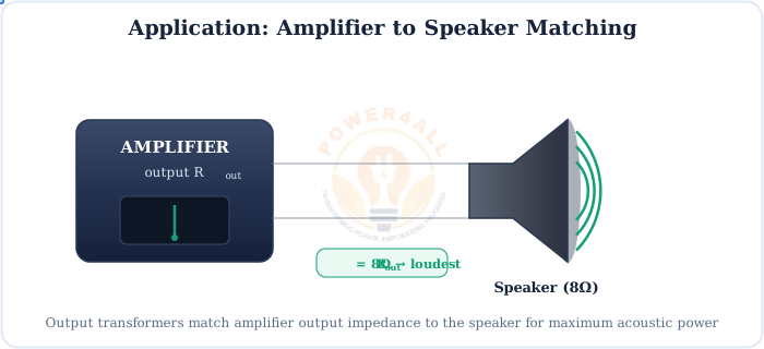
Maximum power transfer rules the world of signals, where every microwatt counts and the power levels are far too small to worry about efficiency.
Antennas & RF
Transmitters, receivers and transmission lines matched to 50Ω for maximum signal and no reflections.
Audio
Amplifier output matched to speaker/headphone impedance for the greatest acoustic power.
Sensors & transducers
Matching a weak sensor to its instrumentation to capture the most signal power.
Communication front-ends
Low-noise amplifiers and mixers matched to squeeze out every bit of received power.
Matched vs Mismatched at a Glance
Put a matched and a mismatched load side by side and the difference is immediate — the matched load simply gets more power.
| Situation | Load vs source | Power to load | Verdict |
|---|---|---|---|
| Under-matched | RL < RS | Below maximum | Too much current wasted in RS |
| Matched | RL = RS | Maximum (Pmax) | Best power transfer |
| Over-matched | RL > RS | Below maximum | Current choked, but more efficient |
Key Terms at a Glance
The essential maximum-power-transfer vocabulary.
RS (source resistance)
The Thévenin/internal resistance of the source.
RL (load resistance)
The resistance receiving the power.
Matching
Making RL = RS (or ZL = ZS*).
Pmax
VTH²/4RS, the peak load power.
Efficiency η
RL/(RS+RL); 50% at the match.
Conjugate match
ZL = ZS*; reactances cancel.
Frequently Asked Questions
Quick, expert answers to the questions people ask most about maximum power transfer.
What is the Maximum Power Transfer Theorem?
It states that a source with a fixed internal (Thévenin) resistance delivers the greatest possible power to a load when the load resistance equals the source resistance, RL = RS. Making the load bigger or smaller reduces the power delivered.
What is the condition for maximum power transfer?
For DC it is RL = RS. For AC it is ZL = ZS* — the load impedance equals the complex conjugate of the source impedance, so the reactances cancel and the resistive parts are equal.
What is the formula for maximum power transfer?
When RL = RS, the maximum power is Pmax = VTH² / 4RS, where VTH is the Thévenin (open-circuit) voltage and RS is the source resistance.
How is the theorem derived?
Write PL = VTH²RL/(RS+RL)², differentiate with respect to RL, and set dPL/dRL = 0. This gives RS − RL = 0, so RL = RS.
What is the efficiency at maximum power transfer?
Only 50%. At the match the source resistance dissipates just as much power as the load, so half the total power is lost as heat in RS.
Why isn't maximum power transfer the same as maximum efficiency?
Maximum power transfer wastes half the power in RS (50% efficiency). For high efficiency you instead make RL >> RS, which delivers less than the maximum power but wastes very little. Power grids chase efficiency; signal circuits chase power.
What is conjugate matching in AC circuits?
Choosing the load impedance to be the complex conjugate of the source: if ZS = R + jX then ZL = R − jX. The reactances cancel, leaving equal resistances and maximum power.
Where is the theorem used in practice?
In antenna and transmission-line matching (50Ω systems), audio amplifier-to-speaker matching, sensor and transducer interfacing, and RF/communication front-ends — anywhere getting the most signal power matters more than efficiency.
What happens if the load is not matched?
The load receives less than the maximum power. In transmission lines a mismatch also reflects part of the wave back toward the source, which can distort signals and stress the source.
Conclusion & Key Takeaways
The Maximum Power Transfer Theorem is a single, elegant idea — match the load to the source — that quietly shapes antennas, audio, sensors and every signal circuit.
Match to peak
RL = RS.
Pmax
VTH²/4RS.
Single peak
The power curve has one maximum.
50% efficient
Half the power heats RS.
AC = conjugate
ZL = ZS*.
Signals, not grids
Used where power is scarce.