Core Losses
The complete guide to core losses (iron losses) — the power wasted as heat inside a magnetic core under AC. From hysteresis loss and eddy-current loss to the Steinmetz formula, lamination, and iron vs copper loss in transformers and motors.
Complete Learning Path — Core Losses
From what core losses are, through hysteresis and eddy-current loss, the formula and lamination, to frequency effects, iron vs copper loss and how to reduce them
What are Core Losses?
Core losses — also called iron losses — are the power turned into heat inside a magnetic core whenever it is magnetised by an alternating current. They happen in the iron of every transformer, motor and inductor.
Core loss is the sum of two parts: hysteresis loss (from repeatedly re-magnetising the material) and eddy-current loss (from tiny currents induced in the core). Because they depend on the AC flux, not the load current, core losses are present even at no load — that is why they are called a constant or no-load loss.
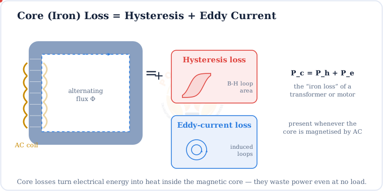
Pc = Ph + Pe
Total core loss = hysteresis loss + eddy-current loss
Hysteresis Loss
Hysteresis loss is the energy spent re-aligning the core’s magnetic domains every AC cycle. Because the material “remembers” its magnetisation (see the B–H curve), it takes the long way round a loop — and that costs energy as heat.
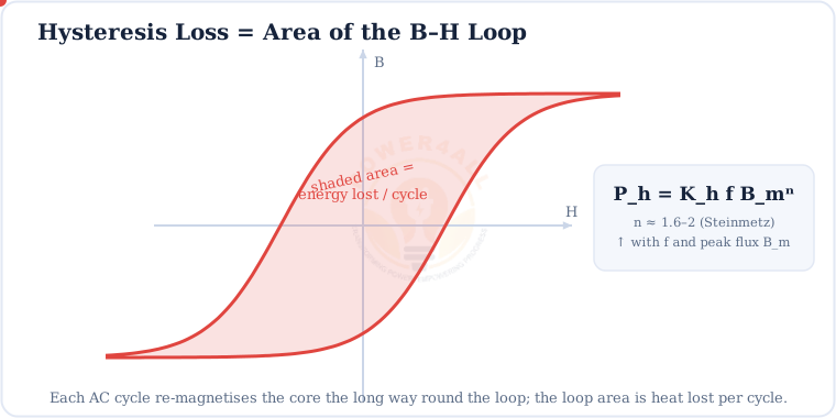
Ph = Kh f Bmn (n ≈ 1.6–2)
Rises with frequency f and peak flux density Bm; Kh and n are Steinmetz material constants
Worked example
If frequency doubles (50 → 100 Hz) at the same peak flux, hysteresis loss:
roughly doubles (Ph ∝ f). Cut the peak flux Bm by 20% and Ph drops by about 30% (since n ≈ 1.6).
Eddy-Current Loss
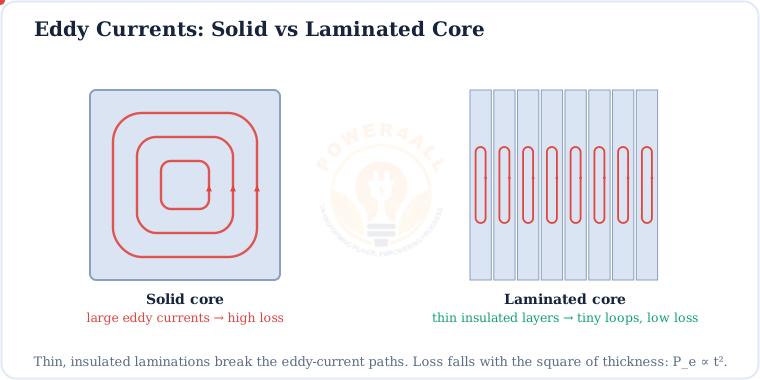
A changing magnetic flux induces voltages inside the conductive core itself, driving little circulating eddy currents. These currents heat the core through its own resistance — wasted power.
Pe = Ke f² Bm² t² / ρ
Rises with f², Bm² and lamination thickness t²; falls with core resistivity ρ
Why cores are laminated
Since Pe ∝ t², halving the lamination thickness cuts eddy loss to a quarter. That is why transformer and motor cores are stacks of thin (0.2–0.5 mm) insulated steel sheets, not solid blocks.
The Core-Loss Formula
Put both mechanisms together and you get the classic Steinmetz core-loss equation — the tool engineers use to predict and minimise iron loss.
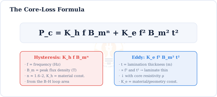
Pc = Kh f Bmn + Ke f² Bm² t²
The full core-loss equation (hysteresis term + eddy-current term)
Specific core loss — watts per kg
Manufacturers quote a material’s specific core loss in W/kg at a stated frequency and flux density (e.g. 1.1 W/kg at 50 Hz, 1.5 T) so designers can pick the lowest-loss steel for the job.
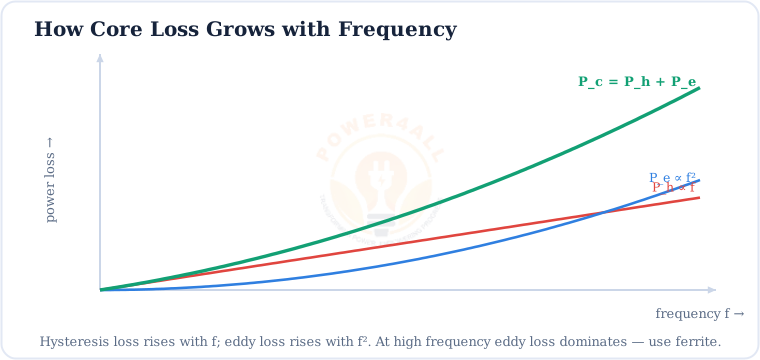
How Core Loss Grows with Frequency
The two loss terms scale differently with frequency, and that decides which material to use.
| Increase… | Hysteresis Ph | Eddy Pe |
|---|---|---|
| Frequency f (×2) | ×2 (∝ f) | ×4 (∝ f²) |
| Peak flux Bm (×2) | ×3 (∝ Bm1.6) | ×4 (∝ Bm²) |
| Lamination t (×2) | no change | ×4 (∝ t²) |
Iron Loss vs Copper Loss & Efficiency
A transformer or motor has two loss families: iron (core) loss and copper loss (I²R in the windings). Together they set the efficiency.
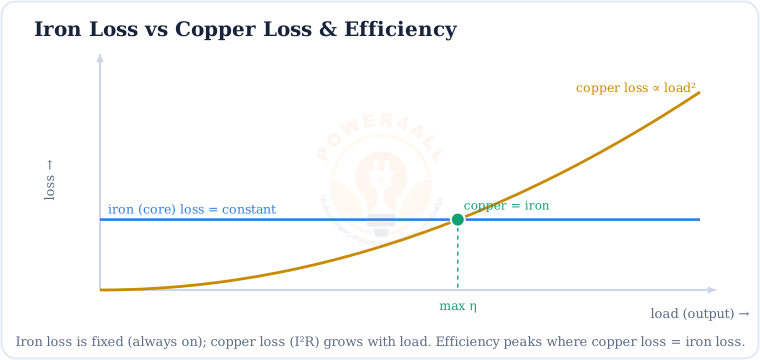
η = Pout / (Pout + Piron + Pcopper) · max η when Pcopper = Piron
Efficiency and the maximum-efficiency condition
Measuring iron loss: the open-circuit test
Apply rated voltage to a transformer with the secondary open. Almost no current flows, so copper loss is negligible and the wattmeter reads essentially the core loss. Copper loss is found separately from the short-circuit test.
How to Reduce Core Losses
Lower core loss means a cooler, more efficient, longer-lasting machine. Here is how engineers cut it.
Thin laminations
Stacks of 0.2–0.5 mm insulated sheets slash eddy loss (Pe ∝ t²).
Silicon steel (CRGO)
Adding silicon raises resistivity and grain-orienting narrows the B–H loop.
Ferrite for high f
Very high resistivity kills eddy loss in SMPS and RF inductors.
Amorphous & nanocrystalline
Ultra-low-loss cores for high-efficiency distribution transformers.
Lower peak flux
Design for a modest Bm — loss falls steeply with flux density.
Good core design
Mitred joints and tight stacking keep flux smooth and loss low.
Key Terms at a Glance
The essential core-loss vocabulary students and engineers search for.
Core / iron loss
Heat in the core under AC (no-load loss).
Hysteresis loss
B–H loop area × f; KhfBmn.
Eddy-current loss
Induced core currents; ∝ f²t².
Lamination
Thin insulated sheets to cut eddy loss.
Steinmetz
The core-loss equation & constants.
Copper loss
I²R in windings; grows with load².
Specific core loss
W/kg at a stated f and Bm.
Open-circuit test
Measures core loss at no load.
Frequently Asked Questions
Quick, expert answers to the questions people ask most about core losses.
What are core losses in simple words?
They are the heat wasted inside the iron core of a transformer or motor when AC magnetises it. There are two kinds — hysteresis loss and eddy-current loss — and together they are called iron loss or no-load loss.
What is the difference between hysteresis and eddy-current loss?
Hysteresis loss comes from re-magnetising the material each cycle and equals the B–H loop area times frequency. Eddy-current loss comes from circulating currents induced in the conductive core. Lamination reduces eddy loss; a better material reduces hysteresis loss.
What is the core-loss formula?
Pc = Ph + Pe = KhfBmn + Kef²Bm²t², where f is frequency, Bm the peak flux density, t the lamination thickness and n ≈ 1.6–2.
Why are cores laminated?
To break up eddy-current paths. Because eddy loss varies with the square of thickness (Pe ∝ t²), thin insulated sheets cut it dramatically compared with a solid core.
Do core losses depend on load?
No — core loss depends on the voltage and frequency (the flux), so it is essentially constant from no load to full load. That is why it is called a constant or no-load loss, unlike copper loss which rises with load.
What is the difference between core loss and copper loss?
Core (iron) loss is in the magnetic core and stays roughly constant; copper loss is the I²R heating in the windings and grows with load². Efficiency peaks where copper loss equals iron loss.
How do you measure core loss?
With the open-circuit (no-load) test: apply rated voltage with the secondary open so copper loss is negligible; the wattmeter then reads essentially the core loss.
Why do high-frequency circuits use ferrite cores?
Because eddy-current loss rises with f², steel cores would overheat at high frequency. Ferrite has very high resistivity, so eddy currents stay tiny — ideal for switch-mode supplies and RF inductors.
Conclusion & Key Takeaways
Core losses are the unavoidable heat of magnetising iron with AC — and minimising them is central to efficient power equipment.
Pc = Ph + Pe
Hysteresis + eddy.
Hysteresis ∝ f
= B–H loop area.
Eddy ∝ f²t²
So laminate the core.
No-load loss
Constant with load.
Max η
Copper loss = iron loss.
Better cores
Silicon steel, ferrite.