Arduino Pro Mini
The smallest, cheapest way to put an Arduino into a finished project. The Arduino Pro Mini runs the same ATmega328P as the Uno and Nano, but strips away the USB — you program it with a cheap FTDI adapter. This guide covers the full board anatomy, a complete pinout with every pin explained, exactly how to upload code over FTDI, the 5V vs 3.3V versions, a Pro Mini vs Uno comparison, and code and mini-projects.
Complete Learning Path — Arduino Pro Mini
From board anatomy and the ATmega328P, to a full pinout with every pin detailed, FTDI programming, power, digital & analog I/O, the buses, Pro Mini vs Uno, code and mini-projects
What is the Arduino Pro Mini?
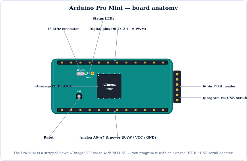
The Arduino Pro Mini is the bare essentials version of the Arduino: the same 8-bit ATmega328P as the Uno and Nano, on the smallest, cheapest board possible — with no USB and almost nothing else.
That makes it perfect for permanent, space-tight builds where you don't need a USB port after uploading. To program it, you plug in a cheap FTDI / USB-serial adapter.
The Brain: ATmega328P
The Pro Mini uses the same ATmega328P as the Uno and Nano — a complete little computer on one chip: a CPU, three kinds of memory and built-in peripherals.
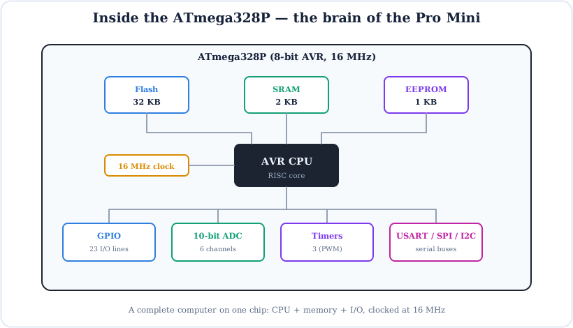
On the 5V board it's clocked at 16 MHz; on the 3.3V board at 8 MHz (a lower voltage can't safely run as fast). Either way the code you write is identical.
Full Arduino Pro Mini Pinout
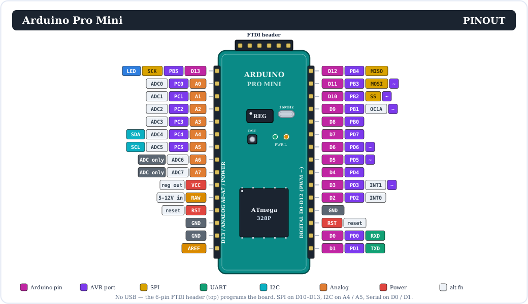
Here is the complete pinout. The digital and analog pins match the Uno/Nano, so the same libraries work — the differences are the missing USB and the RAW / VCC power pins.
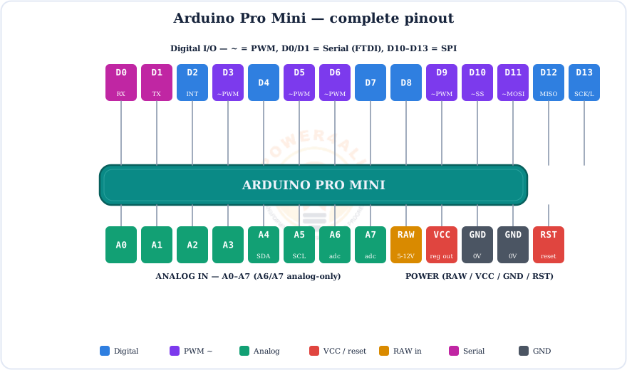
Prefer a simpler view? This colour-coded map groups the pins by function:
Every Pin Explained
Let's go through each group of pins.
Digital pins (D0–D13)
14 general-purpose pins that read or write HIGH or LOW with pinMode(), digitalWrite() and digitalRead(). Each handles ~20 mA (40 mA max). Special roles (same as the Uno):
D0 (RX) & D1 (TX)
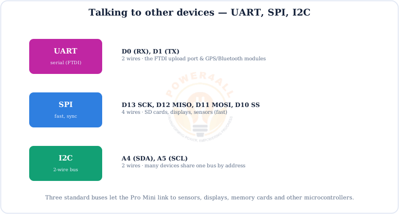
Hardware serial — this is the FTDI upload port; avoid using them while uploading or using Serial.
D2 & D3
External interrupts (INT0, INT1) — attachInterrupt().
D3, 5, 6, 9, 10, 11
PWM (~) outputs — analogWrite(0–255).
D10–D13
SPI bus — 10 = SS, 11 = MOSI, 12 = MISO, 13 = SCK.
D13
Wired to the on-board “L” LED.
Analog input pins (A0–A7)
8 analog inputs (two more than the Uno), each a 10-bit ADC reading 0–VCC as 0–1023:
- A0–A5 can also be used as digital pins; A6 & A7 are analog-only.
- A4 = SDA and A5 = SCL — the hardware I2C bus (same as the Uno).
Power pins (this is where it differs)
| Pin | What it does |
|---|---|
| RAW | Unregulated input — feed a rough voltage (5–12 V for the 5V board) into the on-board regulator. |
| VCC | Regulated logic voltage — either the regulator's output, or feed the exact voltage in here directly. |
| GND | Ground (0 V) — there are two GND pins. |
| RST | Pull LOW to reset; also driven by the FTDI DTR line for auto-reset. |
RAW vs VCC — don't mix them up
Put a rough, higher voltage on RAW (it goes through the regulator). Put only the exact logic voltage (5 V or 3.3 V) on VCC — too much on VCC bypasses the regulator and can destroy the board.
Programming with an FTDI Adapter
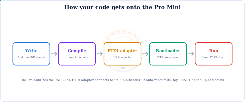
This is the one thing that's really different about the Pro Mini: with no USB on board, you upload code through a cheap external FTDI / USB-serial adapter plugged into the 6-pin header.
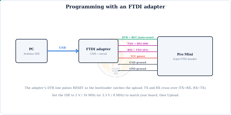
The 6-pin header, in order: DTR, TXO, RXI, VCC, GND, GND (labels vary slightly by board). Connect DTR→DTR, adapter TX→board RXI, adapter RX→board TXO, plus VCC and GND.
Match the voltage!
Set your FTDI adapter's jumper to 5 V for a 5V/16MHz board or 3.3 V for a 3.3V/8MHz board. Feeding 5 V into a 3.3 V board can damage it. In the IDE, pick the matching processor under Tools → Processor.
Powering the Pro Mini
Two ways in: a rough voltage on RAW (through the on-board regulator), or the exact regulated voltage straight into VCC.
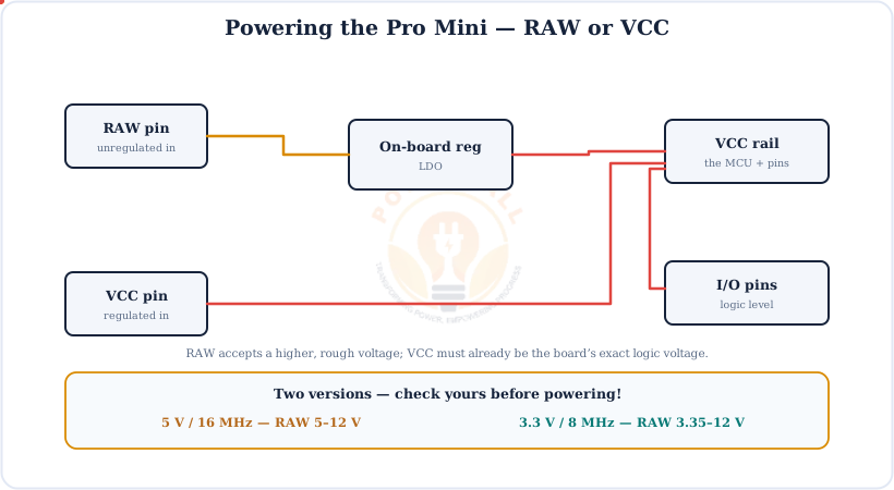
Which version do you have?
The 5V / 16 MHz and 3.3V / 8 MHz boards look almost identical. Check the silkscreen before powering — it sets the logic voltage, the FTDI voltage and the top clock speed.
Digital I/O
Output a HIGH/LOW to drive an LED or relay, or read a HIGH/LOW input from a button or sensor.
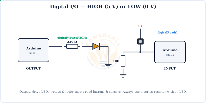
// digital output + input
void setup() {
  pinMode(13, OUTPUT);      // LED pin
  pinMode(2, INPUT);        // button pin
}
void loop() {
  digitalWrite(13, digitalRead(2));   // LED follows the button
}
PWM Output (~)
PWM fakes an analog voltage by switching a pin on and off fast. The Pro Mini has 6 PWM pins: 3, 5, 6, 9, 10, 11.
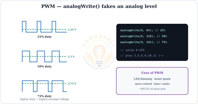
analogWrite(pin, 0–255) on the six ~ pins.// fade an LED on a PWM pin (~9) void setup() { pinMode(9, OUTPUT); } void loop() { for (int v = 0; v <= 255; v++) { analogWrite(9, v); delay(5); } for (int v = 255; v >= 0; v--) { analogWrite(9, v); delay(5); } }
Analog Input (ADC)
The 8 analog pins measure a continuous voltage. The 10-bit ADC turns 0–VCC into 0–1023.
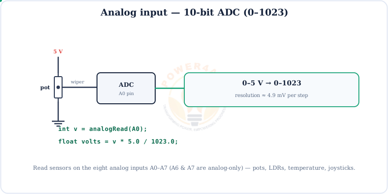
// read a sensor and print volts (5V board)
void setup() { Serial.begin(9600); }
void loop() {
  int raw = analogRead(A0);          // 0..1023 (A6/A7 too)
  float volts = raw * 5.0 / 1023.0;
  Serial.println(volts);
  delay(200);
}
Communication: UART, SPI & I2C
The Pro Mini has the same three buses as the Uno, on the same pins.
The Upload Flow
No USB means the FTDI adapter is part of the chain — its DTR line auto-resets the board so the bootloader catches your sketch.
Pick the right processor
In the IDE choose Board: “Arduino Pro or Pro Mini” and the matching Processor (ATmega328P 5V 16MHz, or 3.3V 8MHz). Wrong choice = a failed upload.
Pro Mini vs Uno
Same brain and code — the Pro Mini simply drops everything you don't strictly need, to be as small and cheap as possible.
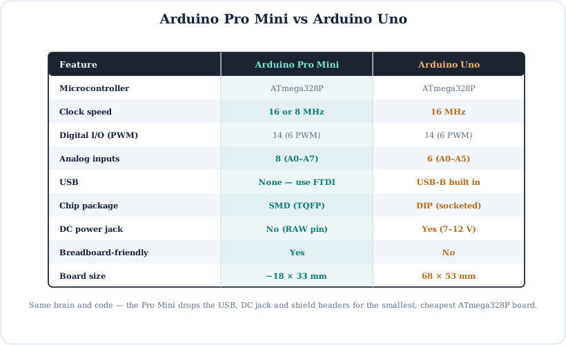
Choose the Pro Mini for finished, space-tight, low-cost builds; the Nano if you want the same tiny size but with USB on board; the Uno for learning and shields.
Code Examples
The everyday building blocks — identical to the Uno and Nano.
1. Blink the on-board LED
void setup() { pinMode(LED_BUILTIN, OUTPUT); }
void loop() {
  digitalWrite(LED_BUILTIN, HIGH); delay(1000);
  digitalWrite(LED_BUILTIN, LOW);  delay(1000);
}
2. Print to the Serial Monitor (through the FTDI adapter)
void setup() {
  Serial.begin(9600);          // via the FTDI adapter
  Serial.println("Hello from the Pro Mini!");
}
void loop() { Serial.println(millis()); delay(1000); }
3. Read a button (internal pull-up)
void setup() {
  pinMode(2, INPUT_PULLUP);           // no external resistor needed
  pinMode(13, OUTPUT);
}
void loop() {
  digitalWrite(13, digitalRead(2) == LOW ? HIGH : LOW);
}
Beginner Mini-Projects
Because it's so small and cheap, the Pro Mini is ideal for leaving inside a finished project. Each sketch below is complete.
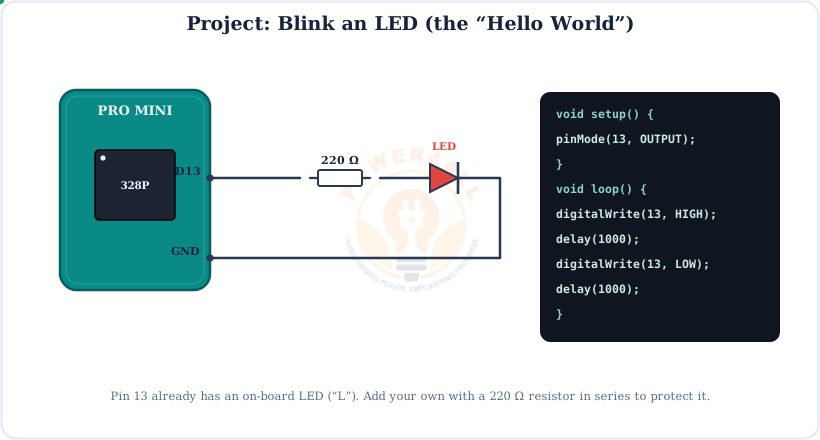
Project 1 — Blink an LED
void setup() { pinMode(13, OUTPUT); }
void loop() {
  digitalWrite(13, HIGH); delay(500);
  digitalWrite(13, LOW);  delay(500);
}
Project 2 — Push-button controlled LED
void setup() {
  pinMode(2, INPUT_PULLUP);
  pinMode(13, OUTPUT);
}
void loop() {
  if (digitalRead(2) == LOW) digitalWrite(13, HIGH);
  else                       digitalWrite(13, LOW);
}
Project 3 — Low-power sensor node
void setup() { Serial.begin(9600); }
void loop() {
  int raw = analogRead(A0);
  Serial.println(raw);
  delay(2000);                   // (add sleep libs to save power)
}
Project 4 — Potentiometer LED dimmer
void setup() { pinMode(9, OUTPUT); }
void loop() {
  int level = map(analogRead(A0), 0, 1023, 0, 255);
  analogWrite(9, level);                // brightness follows the knob
}
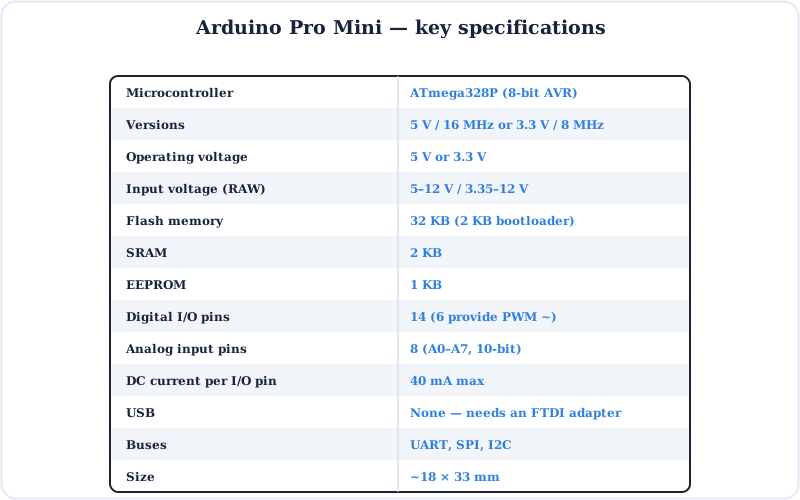
Specifications
The Arduino Pro Mini at a glance.
Key Terms — Glossary
| Term | Meaning |
|---|---|
| FTDI adapter | A USB-to-serial board used to upload code to the Pro Mini (no USB on the board itself). |
| DTR | The adapter line that pulses RESET so the bootloader catches the upload (auto-reset). |
| RAW | Unregulated power input that goes through the on-board regulator. |
| VCC | The board's regulated logic voltage (5 V or 3.3 V). |
| PWM (~) | Pulse-width modulation; 6 pins on the Pro Mini (3, 5, 6, 9, 10, 11). |
| ADC | Analog-to-digital converter; 8 inputs, 10-bit (0–1023). |
| A6 / A7 | Analog-only inputs (no digital function). |
| SPI / I2C | SPI on D10–D13; I2C on A4 (SDA) / A5 (SCL). |
| Bootloader | Small program that lets the board flash itself over serial. |
Frequently Asked Questions
Quick answers to the questions people ask most about the Arduino Pro Mini.
What is the Arduino Pro Mini?
A tiny, low-cost board built around the ATmega328P with no USB. You program it with an external FTDI / USB-serial adapter. It comes in 5V/16MHz and 3.3V/8MHz versions and has 14 digital pins (6 PWM) and 8 analog inputs.
How do I program it?
Connect an FTDI adapter to the 6-pin header: DTR, TXO, RXI, VCC and two GND. TX and RX cross over (adapter TX → board RXI, adapter RX → board TXO), and DTR auto-resets the board. Match the adapter voltage to your board, pick “Arduino Pro or Pro Mini” and the right processor, and Upload.
Pro Mini vs Nano — what's different?
Same ATmega328P, same 14 digital + 8 analog pins. The Nano has USB on board; the Pro Mini has none, so it's smaller and cheaper but needs an FTDI adapter. The Pro Mini also comes in a 3.3V/8MHz version.
What are the 5V and 3.3V versions?
Two builds: 5V at 16 MHz, and 3.3V at 8 MHz. It sets the logic voltage, the FTDI voltage you must use, and the top clock speed. Always check which one you have.
How do I power it (RAW vs VCC)?
Feed a rough voltage (about 5–12 V for the 5V board) into RAW and the regulator makes the logic voltage. Or feed the exact regulated voltage straight into VCC. Don't put a high voltage on VCC — that bypasses the regulator.
Where are SPI and I2C?
Same as the Uno: SPI on 13 (SCK), 12 (MISO), 11 (MOSI), 10 (SS); I2C on A4 (SDA) / A5 (SCL). Hardware serial (and the FTDI upload) is on D0/D1.
How many analog pins does it have?
Eight: A0–A7. A0–A5 can also be digital; A6 and A7 are analog-only. Read them with analogRead(A6) and so on.
Why won't my Pro Mini upload?
Check the FTDI wiring (TX/RX must cross), that DTR is connected, and that the adapter voltage matches the board. Pick the correct processor in the IDE. If auto-reset fails, press RESET just as the upload begins.
Conclusion & Key Takeaways
The Arduino Pro Mini is the Uno's brain shrunk to the bare minimum — perfect once your project is finished and you no longer need a USB port.
ATmega328P
Same as Uno/Nano.
No USB
Program via FTDI.
14 + 8 pins
Digital + analog.
RAW / VCC
Two power inputs.
5V & 3.3V
Two versions.
Tiny & cheap
Great for builds.