Capacitor Bank (Power Factor Correction)
The bank of power capacitors that supplies leading reactive power (kVAR) to cancel the lagging kVAR of motors and transformers — raising the power factor towards unity. Learn what a capacitor bank is, how it works, how to size its kVAR, fixed vs automatic (APFC) vs detuned banks, star vs delta connection, benefits and cautions.
Complete Learning Path — Capacitor Bank (PFC)
From what a capacitor bank is and why power factor matters, to kVAR sizing, types, connection, benefits and cautions
What Is a Capacitor Bank?
A capacitor bank is a group of power capacitors connected together and installed at a load or busbar to supply leading reactive power (measured in kVAR) for power factor correction (PFC).
Inductive loads — induction motors, transformers, welders, chokes and fluorescent ballasts — draw a lagging reactive current that does no useful work but still loads the supply. A capacitor bank draws a leading current that is almost the mirror image of that lagging current, so when it is connected in parallel with the load it supplies the reactive power locally. The utility then feeds less current and less apparent power (kVA) for the same real power (kW), and the power factor rises towards unity.
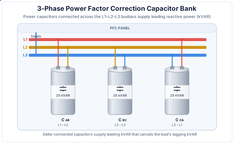
The one-line idea
The load needs reactive power; instead of shipping it all the way from the utility, the capacitor bank supplies it right at the load. Same real work done — far less current.
Why Power Factor Matters — The Power Triangle
Power factor is the ratio of real power (kW) to apparent power (kVA), and the power triangle shows exactly how a capacitor bank improves it.
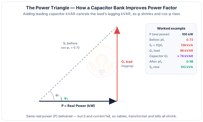
The three sides are real power P (kW, the useful work), reactive power Q (kVAR, the magnetising power inductive loads need) and apparent power S (kVA, what the utility actually supplies), with S² = P² + Q² and power factor = cos φ = P / S. A low power factor means a big angle φ: the same P is delivered with a much larger S and current. Because the capacitor’s reactive power is the opposite sign to the load’s, adding QC pulls the resultant reactive power down, shrinks φ, and raises cos φ. See real, reactive & apparent power for the full picture.
Why the utility charges for it
A poor power factor forces the utility to build cables and transformers for the extra current that carries no real energy — so tariffs add a power-factor penalty or bill on kVA demand. Correcting it removes that penalty.
How a Capacitor Bank Corrects Power Factor
A capacitor bank is connected in parallel (shunt) with the load at the point of common coupling, where it supplies the reactive current locally so the utility feeds less line current.
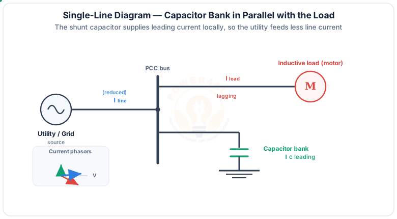
In phasor terms the capacitor current IC leads the voltage by 90°, while the inductive load current Iload lags it. Adding them tip-to-tail gives a resultant line current Iline that is smaller and much closer to being in phase with the voltage — which is a higher power factor. Crucially, the capacitor only supplies reactive power; it consumes almost no real power, so the useful output of the motor is untouched.
Worked example — current saved
A 400 V, 100 kW load at power factor 0.72 draws S = 100/0.72 = 139 kVA → about 200 A per phase. Correct it to 0.98 and S = 102 kVA → about 147 A. Same 100 kW of work, but ~27% less current in every cable, breaker and transformer upstream.
Sizing a Capacitor Bank — kVAR & Capacitance
The size of a capacitor bank is set by how much reactive power (kVAR) it must supply to move the power factor from its present value to the target.
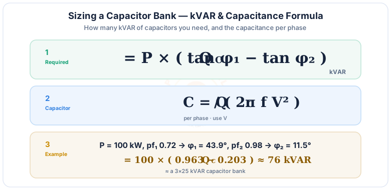
Worked example — how many kVAR?
Correct P = 100 kW from pf1 = 0.72 to pf2 = 0.98:
- φ1 = cos−1(0.72) = 43.9° → tan φ1 = 0.963
- φ2 = cos−1(0.98) = 11.5° → tan φ2 = 0.203
- QC = 100 × (0.963 − 0.203) ≈ 76 kVAR → e.g. a 3×25 kVAR bank
For a quick answer, try the Power Factor Calculator.
Types — Fixed, Automatic (APFC) & Detuned
Capacitor banks range from an always-on fixed bank to a stepped automatic (APFC) bank and a harmonic-safe detuned bank.
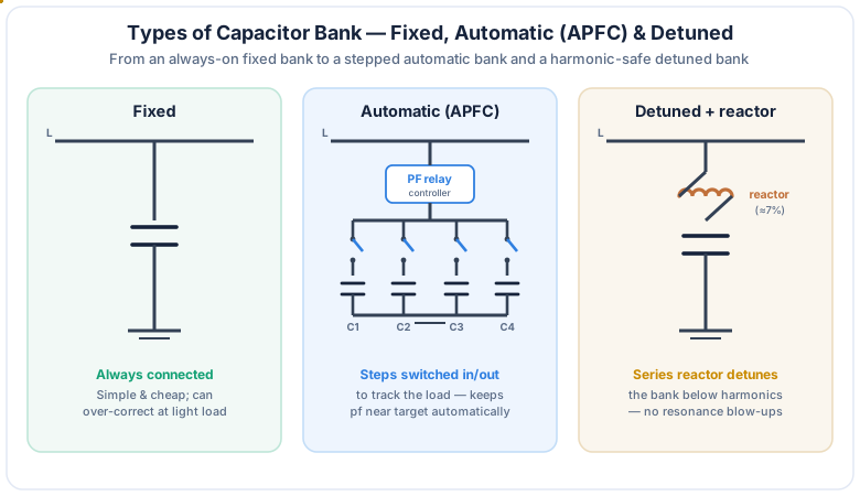
Fixed bank
Permanently connected, supplies constant kVAR. Simple and cheap; best where the load is steady. Can over-correct at light load.
Automatic (APFC)
A power-factor relay switches capacitor steps in and out via contactors so the kVAR tracks the changing load and holds the PF near target.
Thyristor-switched
An RTPFC bank switches steps electronically at the voltage zero-crossing for transient-free, fast correction on rapidly varying loads.
Detuned (with reactor)
A ~7% series reactor tunes each step below the lowest harmonic to avoid resonance where drives and rectifiers create harmonics.
Star vs Delta Connection
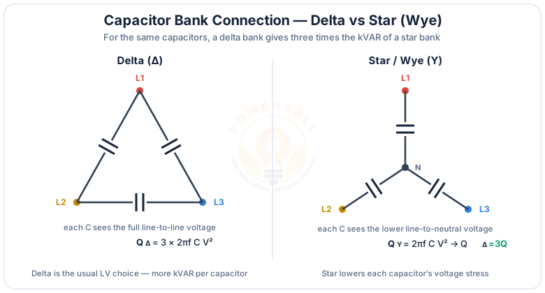
Three-phase capacitor banks are connected either in delta or in star (wye), and the choice changes the kVAR per capacitor and the voltage stress.
| Delta (Δ) | Star / Wye (Y) | |
|---|---|---|
| Voltage on each C | Line-to-line (VLL) | Line-to-neutral (VLL/√3) |
| kVAR (same C) | QΔ = 3 × QY | QY = 2πfCV² |
| Typical use | Low-voltage banks (more kVAR/cap) | Higher voltage; lower cap stress |
| Note | Most common LV PFC choice | Neutral can be earthed or floating |
Benefits of a Capacitor Bank
Correcting power factor pays for itself — the reduced current ripples benefits all the way back to the transformer.
Lower electricity bills
Removes power-factor penalties and cuts kVA demand charges on the tariff.
Lower losses
Less current means lower I²R losses in cables and transformer windings.
Released capacity
Frees up kVA in existing transformers and cables so they can carry more real load.
Better voltage
Reduced reactive current improves voltage regulation at the load end.
Cautions & Protection
A capacitor bank is powerful but must be applied carefully — watch over-correction, harmonics and safe discharge.
Over-correction
Too much fixed kVAR at light load makes the PF leading and can raise voltage — use automatic switching.
Harmonics & resonance
A plain bank can resonate with supply inductance and amplify harmonics — use a detuned bank with reactors.
Discharge resistors
Capacitors hold charge; discharge resistors bleed it off safely before anyone touches or re-energises them.
Inrush & switching
Switching capacitors draws a high inrush; use dedicated capacitor-duty contactors or damping reactors.
Protection & earthing
Fuses/MCCBs, overload and unbalance protection, plus correct earthing of the bank.
Ambient & rating
Respect the capacitor voltage, temperature and over-current ratings; harmonics raise the true rms current.
Key Terms at a Glance
The essential capacitor-bank and power-factor vocabulary engineers and students search for.
Capacitor bank
Group of power capacitors supplying kVAR.
kVAR
Reactive power the bank supplies.
Power factor
cos φ = real / apparent power.
APFC
Automatic power factor correction (stepped).
Detuned reactor
Series reactor that avoids resonance.
Over-correction
Leading PF from too much kVAR at light load.
Frequently Asked Questions
Quick, expert answers to the questions people ask most about capacitor banks and power factor correction.
What is a capacitor bank?
A capacitor bank is a group of power capacitors connected together and installed at a load or busbar to supply leading reactive power, measured in kVAR, for power factor correction. Inductive loads such as motors and transformers draw lagging reactive power; the capacitor bank supplies that reactive power locally, so the utility feeds less apparent power and less current at the same real power, raising the power factor towards unity.
How does a capacitor bank improve power factor?
A capacitor draws a leading current that is almost the mirror image of the lagging current an inductive load draws. When a capacitor bank is connected in parallel with the load, its leading reactive power cancels most of the load’s lagging reactive power. The real power stays the same, but the reactive component and therefore the apparent power and line current fall, so the power factor rises towards unity.
Why is a low power factor a problem?
A low power factor means the same real power is delivered with more current and more apparent power (kVA). That larger current causes higher losses in cables and transformers, uses up system capacity, can drop the voltage, and usually triggers a power-factor penalty or higher demand charge on the electricity bill. Correcting the power factor with a capacitor bank removes most of these penalties.
How do I calculate the kVAR of capacitor bank I need?
Use QC = P (tan φ1 − tan φ2), where P is the real power in kilowatts, φ1 is the angle of the present power factor and φ2 is the angle of the target power factor. For example, to correct 100 kW from a power factor of 0.72 (φ1 = 43.9°) to 0.98 (φ2 = 11.5°), QC = 100 × (0.963 − 0.203), which is about 76 kVAR. The capacitance per phase is then C = QC / (2πfV²).
What is the difference between a fixed and an automatic (APFC) capacitor bank?
A fixed capacitor bank is permanently connected and always supplies the same kVAR, which is simple and cheap but can over-correct when the load is light. An automatic power factor correction (APFC) bank is divided into steps that a power-factor controller switches in and out through contactors or thyristors, so the supplied kVAR follows the changing load and keeps the power factor near the target at all times.
What is a detuned capacitor bank and why use a reactor?
A detuned capacitor bank places a small series reactor in front of each capacitor step, usually around 7 percent, which shifts the resonant frequency of the reactor-capacitor combination below the lowest significant harmonic. This stops the bank from resonating with system harmonics, which would otherwise amplify harmonic currents and can destroy capacitors. Detuned banks are used wherever there are significant harmonic-producing loads such as variable-frequency drives.
Should a capacitor bank be connected in star or delta?
In a delta connection each capacitor is across the full line-to-line voltage, so for the same capacitance a delta bank supplies three times the kVAR of a star bank; delta is the usual choice for low-voltage banks because it gives more kVAR per capacitor. In a star (wye) connection each capacitor sees only the line-to-neutral voltage, which lowers the voltage stress on each capacitor and is often used at higher voltages.
Where is a capacitor bank installed or connected?
A capacitor bank is connected in parallel (shunt) with the load. It can be placed at an individual large motor (individual correction), on a group of loads or a distribution board (group correction), or at the main incomer or busbar of the plant (central correction). Central automatic banks at the main busbar are the most common for whole-plant power factor correction.
What are the benefits of a capacitor bank?
Correcting power factor with a capacitor bank reduces the current and apparent power drawn from the supply, which lowers electricity bills by removing power-factor penalties and reducing demand charges, cuts losses in cables and transformers, releases spare capacity so existing transformers and cables can carry more real load, and can improve voltage regulation at the load.
Can a capacitor bank cause problems such as over-correction or resonance?
Yes. If too much kVAR stays connected at light load the power factor can become leading (over-correction), which can raise the voltage and cause its own penalty. A plain capacitor bank can also resonate with the supply inductance at a harmonic frequency and amplify harmonic currents. These problems are avoided by switching the bank automatically to match the load and by using detuned banks with series reactors where harmonics are present.
Why do capacitor banks need discharge resistors?
A capacitor holds a charge after it is disconnected, so a capacitor bank needs discharge resistors (or discharge reactors) to bleed off that stored charge safely within a set time. This protects people from a dangerous stored voltage and prevents a capacitor from being reconnected while still charged, which could cause a large switching transient.
What is the difference between a capacitor bank and a synchronous condenser?
Both supply leading reactive power to correct power factor, but a capacitor bank is a static device that supplies kVAR in fixed or switched steps and is cheap and low-loss, while a synchronous condenser is a rotating machine whose reactive output can be varied smoothly and continuously. Capacitor banks are by far the most common choice for ordinary industrial and commercial power factor correction; synchronous condensers are used mainly in large power systems needing continuous, adjustable reactive support.
Conclusion & Key Takeaways
A capacitor bank is the workhorse of power factor correction: it supplies leading kVAR right at the load, so the same real work is done with less current, lower bills and freed-up capacity.
Supplies kVAR
Leading reactive power locally.
Raises PF
cos φ → unity, smaller S.
QC = P(tanφ1−tanφ2)
Sizes the bank.
Fixed / APFC / detuned
Match to the load.
Delta = 3× star
kVAR per capacitor.
Mind harmonics
Detune & discharge safely.