Master Kirchhoff's Laws
Complete guide to Kirchhoff's Current Law (KCL) and Voltage Law (KVL) - the fundamental principles of circuit analysis that every electronics engineer must know
Complete Learning Path - Kirchhoff's Laws Fundamentals to Applications
Navigate through comprehensive coverage of Kirchhoff's Laws from basic principles to advanced applications
Introduction to Kirchhoff's Laws
Kirchhoff's Laws are the cornerstone of electrical circuit analysis, providing the mathematical foundation for understanding how current flows and voltage distributes in any electrical network. Named after German physicist Gustav Kirchhoff who formulated them in 1845, these laws are based on fundamental physical principles and are essential for every electronics engineer, student, and hobbyist.
Why These Laws Matter
Before Kirchhoff's Laws, analyzing electrical circuits was largely empirical and limited to simple configurations. These laws transformed circuit analysis into a systematic, mathematical discipline that allows engineers to predict and control electrical behavior with precision.
The Physical Foundation
Kirchhoff's Laws aren't arbitrary mathematical rules - they're direct consequences of fundamental physics principles that govern our universe.
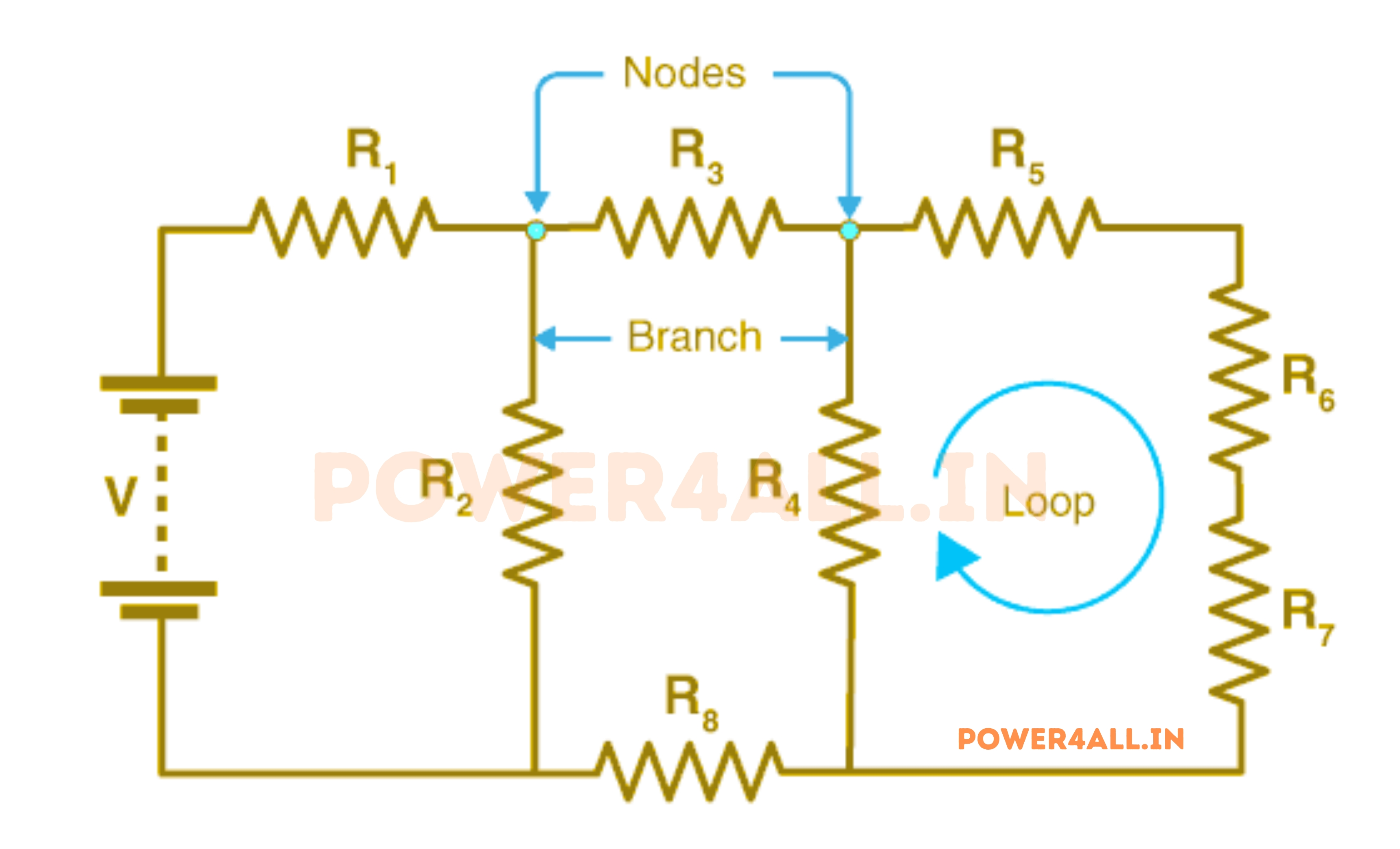
What are Kirchhoff's Laws?
Kirchhoff's Laws consist of two fundamental principles that describe the behavior of electric current and voltage in circuits. These laws provide the mathematical tools needed to analyze any electrical network, no matter how complex.
The Two Fundamental Laws
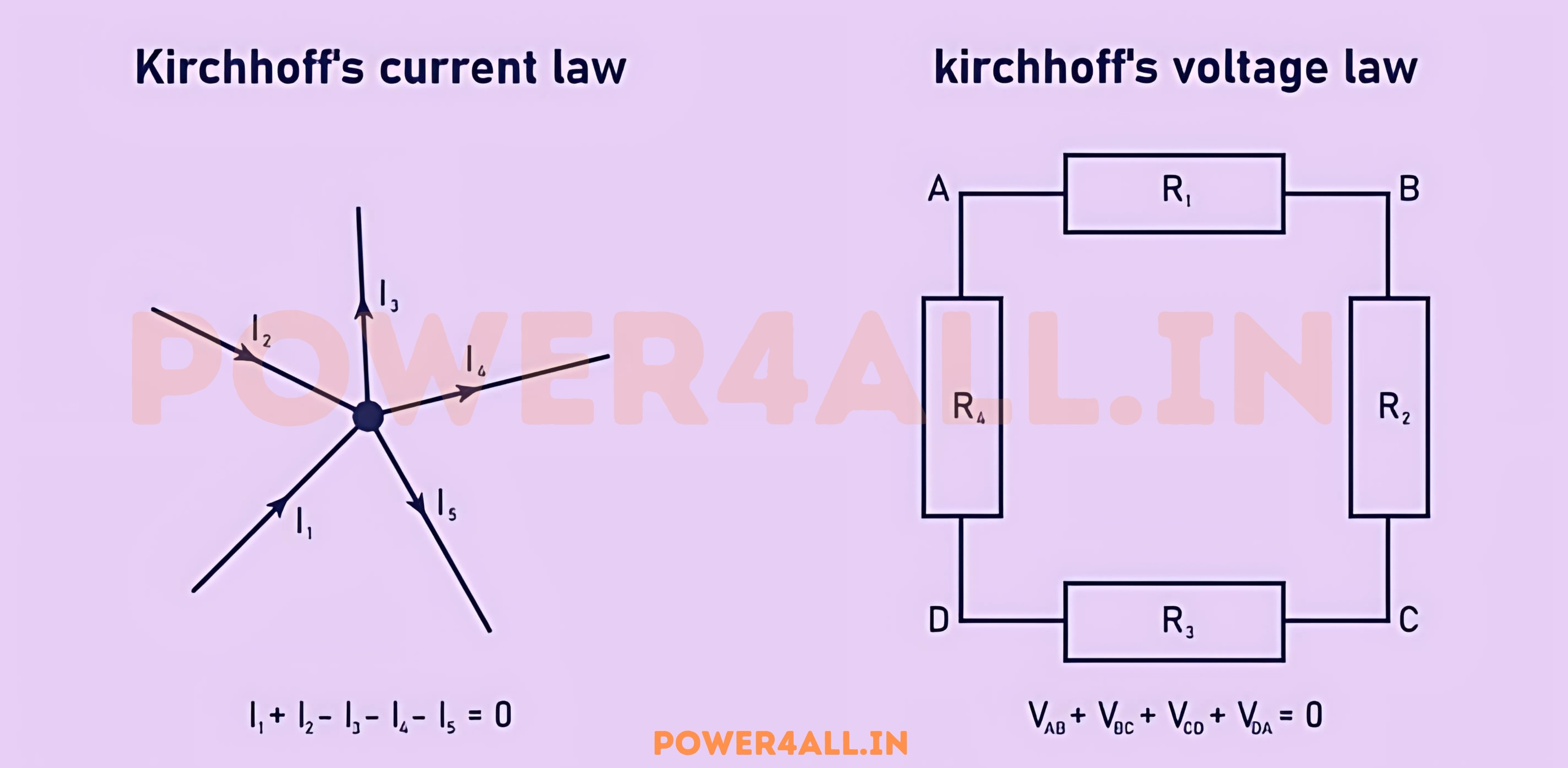
Kirchhoff's Current Law (KCL)
Also known as: Kirchhoff's First Law, Junction Rule, or Node Law
ΣI_in = ΣI_out
Current entering = Current leaving
Simple Explanation
At any junction (node) in a circuit, the total current flowing in must equal the total current flowing out. Think of it like water at a pipe junction - water flowing in equals water flowing out.
Why This Happens
- Based on conservation of electric charge
- Charge cannot accumulate at a junction
- What goes in must come out
Kirchhoff's Voltage Law (KVL)
Also known as: Kirchhoff's Second Law, Loop Rule, or Mesh Law
ΣV = 0
Sum of voltages around any loop = 0
Simple Explanation
If you start at any point in a circuit and trace around any closed loop, adding up all voltage rises and drops, the total will always be zero. It's like hiking - if you start and end at the same elevation, your net elevation change is zero.
Why This Happens
- Based on conservation of energy
- Energy supplied = Energy consumed
- No net energy gain around a closed path
Intuitive Analogies
Understanding Through Everyday Examples
Water Flow Analogy (KCL)
Imagine a water pipe system with a junction where one large pipe splits into three smaller pipes.
Hiking Elevation Analogy (KVL)
Think of voltage as elevation and current as a hiker walking around a circular trail.
Mathematical Check:
+500ft - 200ft - 300ft = 0 ✓ (KVL satisfied)
When and Where to Apply Each Law
Kirchhoff's Current Law (KCL) - Complete Guide
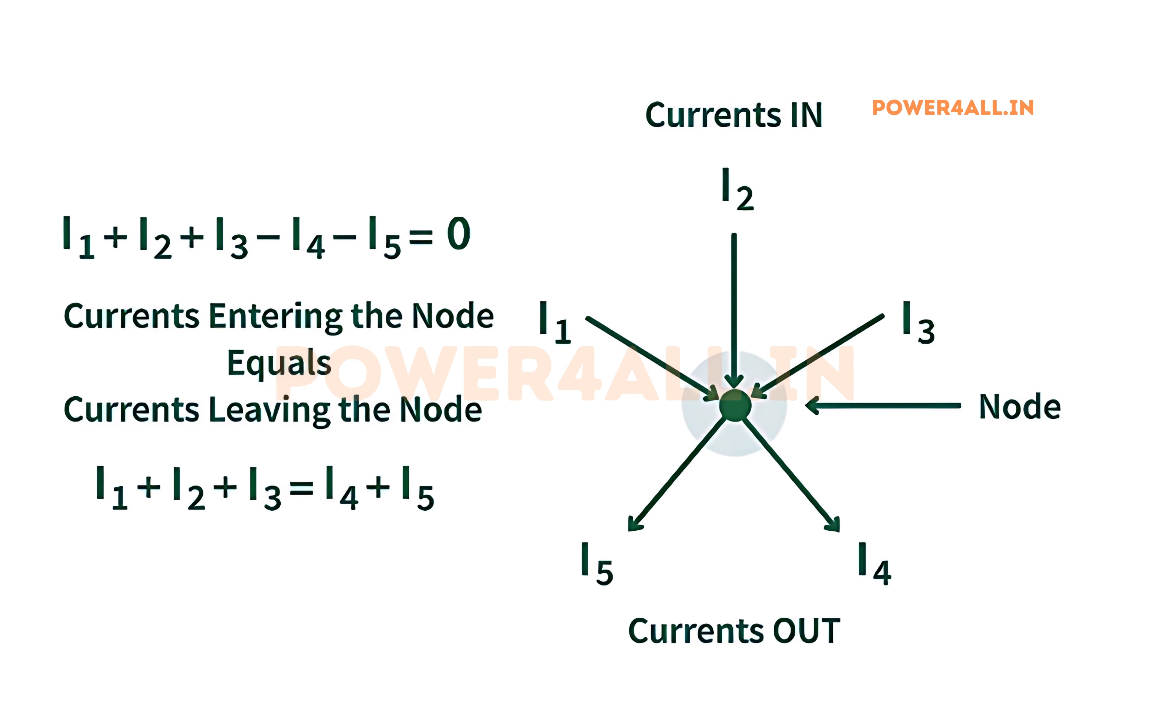
Kirchhoff's Current Law states that the algebraic sum of currents entering and leaving any node in a circuit equals zero. This law is the mathematical expression of charge conservation and is fundamental to understanding how current distributes in electrical networks.
Mathematical Formulation
∑I = 0
Algebraic sum of all currents at a node
Alternative Forms
- ∑I_in = ∑I_out (Sum of currents in = Sum of currents out)
- I₁ + I₂ + I₃ + ... + Iₙ = 0 (Algebraic sum form)
- ∑I_entering - ∑I_leaving = 0 (Sign convention form)
Step-by-Step Application Process
How to Apply KCL Systematically
Example Node Analysis
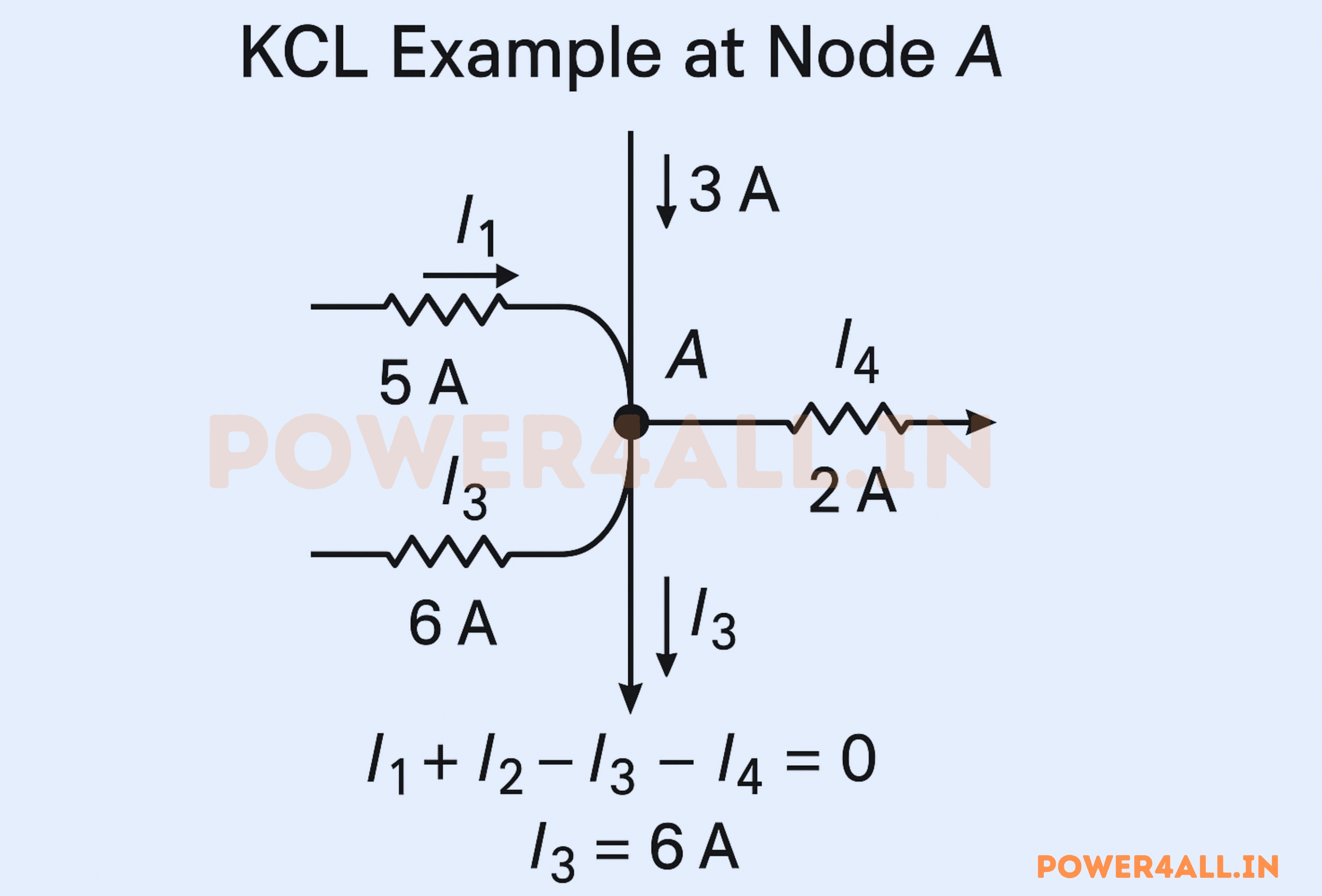
Node A Analysis:
Currents entering: I₁ = 5A, I₂ = 3A
Currents leaving: I₃ = ?, I₄ = 2A
KCL Application: I₁ + I₂ - I₃ - I₄ = 0
Solution: 5 + 3 - I₃ - 2 = 0 → I₃ = 6A
Practical Examples
Simple Three-Branch Node
Problem: Find the unknown current I₃
Complex Multi-Node Circuit
Problem: Analyze a circuit with multiple unknown currents
Special Cases and Considerations
Common Mistakes and How to Avoid Them
Kirchhoff's Voltage Law (KVL) - Complete Guide
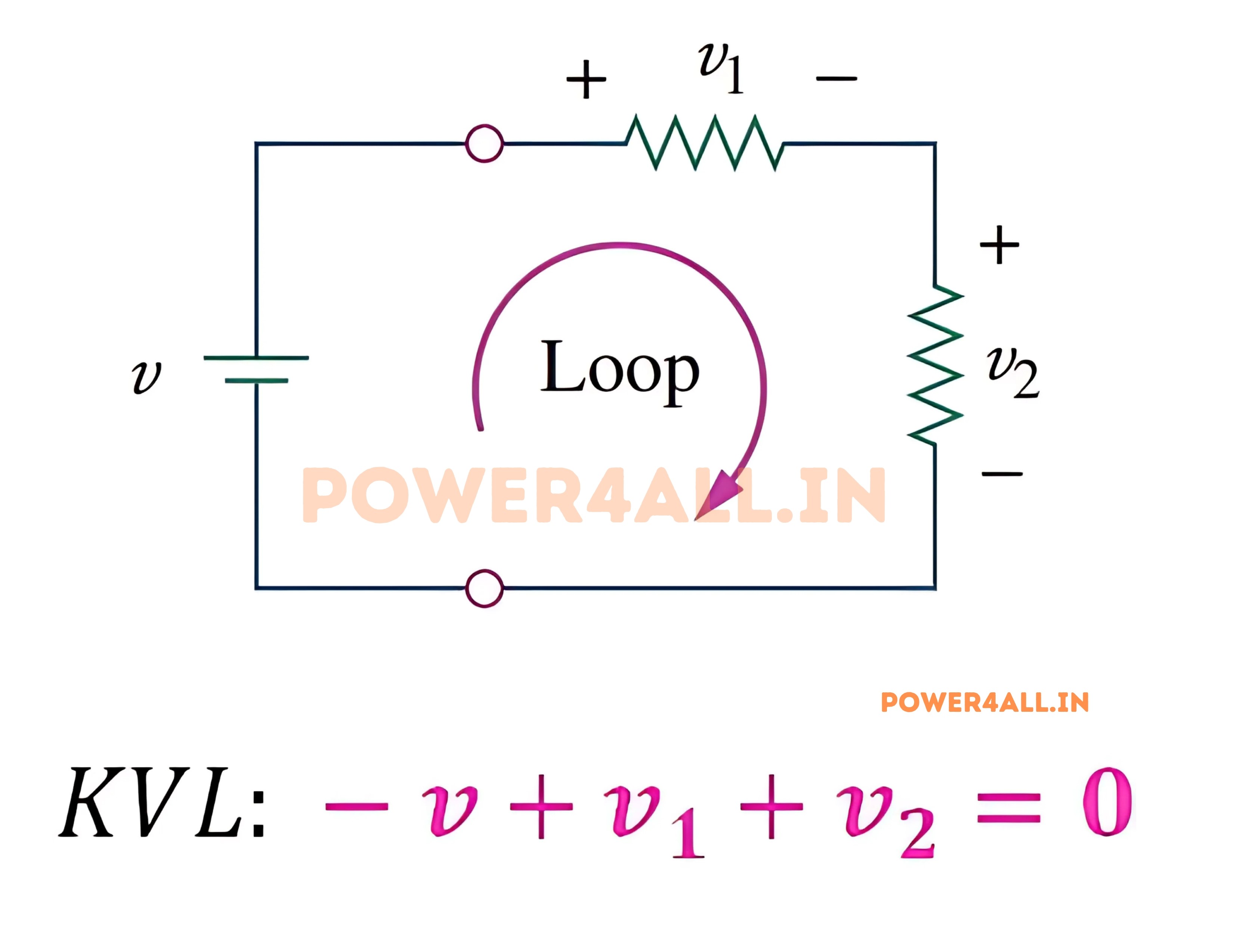
Kirchhoff's Voltage Law states that the algebraic sum of all voltages around any closed loop in a circuit equals zero. This law embodies the conservation of energy principle and provides the foundation for analyzing voltage distribution in electrical networks.
Mathematical Formulation
∑V = 0
Sum of all voltages around any closed loop
Alternative Forms
- ∑V_rises = ∑V_drops (Voltage rises = Voltage drops)
- V₁ + V₂ + V₃ + ... + Vₙ = 0 (Algebraic sum form)
- ∑V_sources = ∑V_loads (Energy balance form)
Understanding Voltage Rises and Drops
What Creates Voltage Rises and Drops?
Voltage Rises (Energy Sources)
Components that add energy to the circuit
Common Voltage Sources
- Batteries: Chemical energy → Electrical energy
- Generators: Mechanical energy → Electrical energy
- Solar cells: Light energy → Electrical energy
- Power supplies: AC → DC conversion
Voltage Drops (Energy Consumers)
Components that consume energy from the circuit
Common Voltage Drops
- Resistors: Electrical → Heat energy
- LEDs: Electrical → Light energy
- Motors: Electrical → Mechanical energy
- Speakers: Electrical → Sound energy
Step-by-Step KVL Application
Worked Examples
Simple Series Circuit
Find the voltage across the unknown resistor
Circuit: 24V battery + 10Ω resistor + R₂ (unknown) + 6Ω resistor
Given: Current I = 2A (same throughout series circuit)
Multi-Loop Circuit
Apply KVL to multiple loops simultaneously
Circuit: Two voltage sources, three resistors in a complex network
Given: V₁ = 12V, V₂ = 8V, R₁ = 4Ω, R₂ = 6Ω, R₃ = 3Ω
Practical Applications of KVL
Sign Conventions and Best Practices
Practical Applications of Kirchhoff's Laws
Kirchhoff's Laws aren't just academic concepts - they're the foundation of virtually every electrical system around us. From the smartphone in your pocket to the power grid that lights your home, these laws enable engineers to design, analyze, and troubleshoot electrical systems reliably.
Consumer Electronics
Smartphone Circuits
Complex multi-voltage systems
KCL Applications
- Battery current distribution: Current splits between CPU, display, radio, and sensors
- Charging circuits: Current balancing in multi-cell batteries
- Power management: Dynamic current allocation based on usage
KVL Applications
- Voltage regulators: Step down from 3.7V battery to 1.8V, 1.2V, etc.
- Display backlighting: LED voltage drops in series/parallel combinations
- Audio amplifiers: Signal path voltage analysis
Automotive Electronics
Safety-critical electrical systems
Engine Management
- Sensor networks: KCL for current distribution to oxygen sensors, temp sensors
- Injector control: KVL for precise voltage timing to fuel injectors
- Ignition system: High-voltage coil analysis using KVL
Safety Systems
- ABS braking: Wheel speed sensor current analysis
- Airbag deployment: Critical timing based on voltage/current calculations
- Battery management: 12V/48V system voltage monitoring
Home Electrical Systems
Power distribution and safety
Circuit Breaker Design
- Load calculation: KCL determines total current on each circuit
- Voltage drop analysis: KVL ensures proper voltage at outlets
- Ground fault detection: KCL detects current imbalances
Smart Home Integration
- Energy monitoring: Smart meters use Kirchhoff's Laws for accurate measurement
- Solar panel systems: Grid-tie inverter design and analysis
- Electric vehicle charging: High-power charging station design
Industrial and Power Systems
Large-Scale Electrical Systems
Power Generation and Distribution
Electrical Grid Management
Balancing supply and demand across vast networks
- Load flow analysis: KCL and KVL determine power flow through transmission lines
- Grid stability: Voltage regulation using transformer tap settings
- Fault analysis: Short circuit current calculations for protection
- Renewable integration: Solar and wind farm connection analysis
P_generated = P_consumed + P_losses
Power balance in electrical grids
Industrial Motor Control
Precise control of industrial machinery
- Variable frequency drives: Complex switching circuits analyzed with Kirchhoff's Laws
- Motor starting: Current rush limiting using reactance calculations
- Regenerative braking: Energy recovery system design
- Multi-motor coordination: Load sharing in parallel motor systems
Telecommunications Infrastructure
Modern communication systems rely heavily on Kirchhoff's Laws for signal integrity and power distribution:
Circuit Analysis Methods Using Kirchhoff's Laws
Kirchhoff's Laws form the foundation of systematic circuit analysis methods. These techniques allow engineers to solve complex circuits with multiple sources, nodes, and loops by converting the physical circuit into a set of mathematical equations.
Node Voltage Analysis (Nodal Analysis)
Method Overview
Node voltage analysis uses KCL as the primary tool to solve circuits. We assign voltage variables to each node and write KCL equations based on currents flowing into and out of each node.
When to Use Nodal Analysis
- Fewer nodes than loops: More efficient than mesh analysis
- Current sources present: Easily handled in nodal analysis
- Need node voltages: Direct solution for voltage values
- Computer analysis: Easier to program and automate
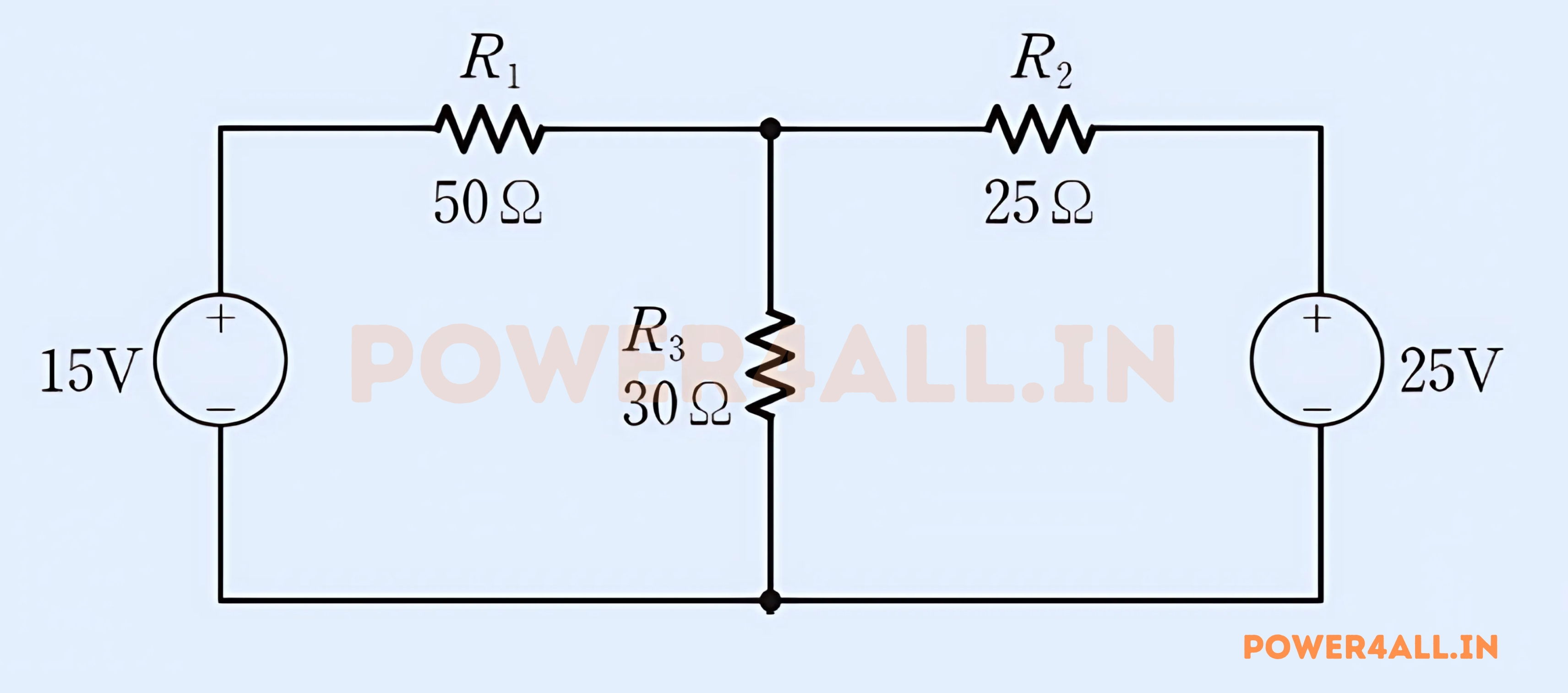
Detailed Nodal Analysis Example
Example Circuit
Circuit Description: Two voltage sources (15V, 25V), three resistors (50Ω, 25Ω, 30Ω), find all node voltages and branch currents.
Mesh Current Analysis (Loop Analysis)
Method Overview
Mesh analysis uses KVL as the primary tool to solve circuits. We assign current variables to each mesh (loop) and write KVL equations for the voltage drops around each loop.
When to Use Mesh Analysis
- Fewer loops than nodes: More efficient than nodal analysis
- Voltage sources present: Directly incorporated in mesh equations
- Need loop currents: Direct solution for current values
- Planar circuits: Works best with circuits that can be drawn without crossing wires
Comparison of Analysis Methods
Advanced Techniques
Worked Examples: Step-by-Step Solutions
Let's work through comprehensive examples that demonstrate how to apply Kirchhoff's Laws to solve real circuits. These examples progress from simple to complex, showing different techniques and common scenarios you'll encounter in practice.
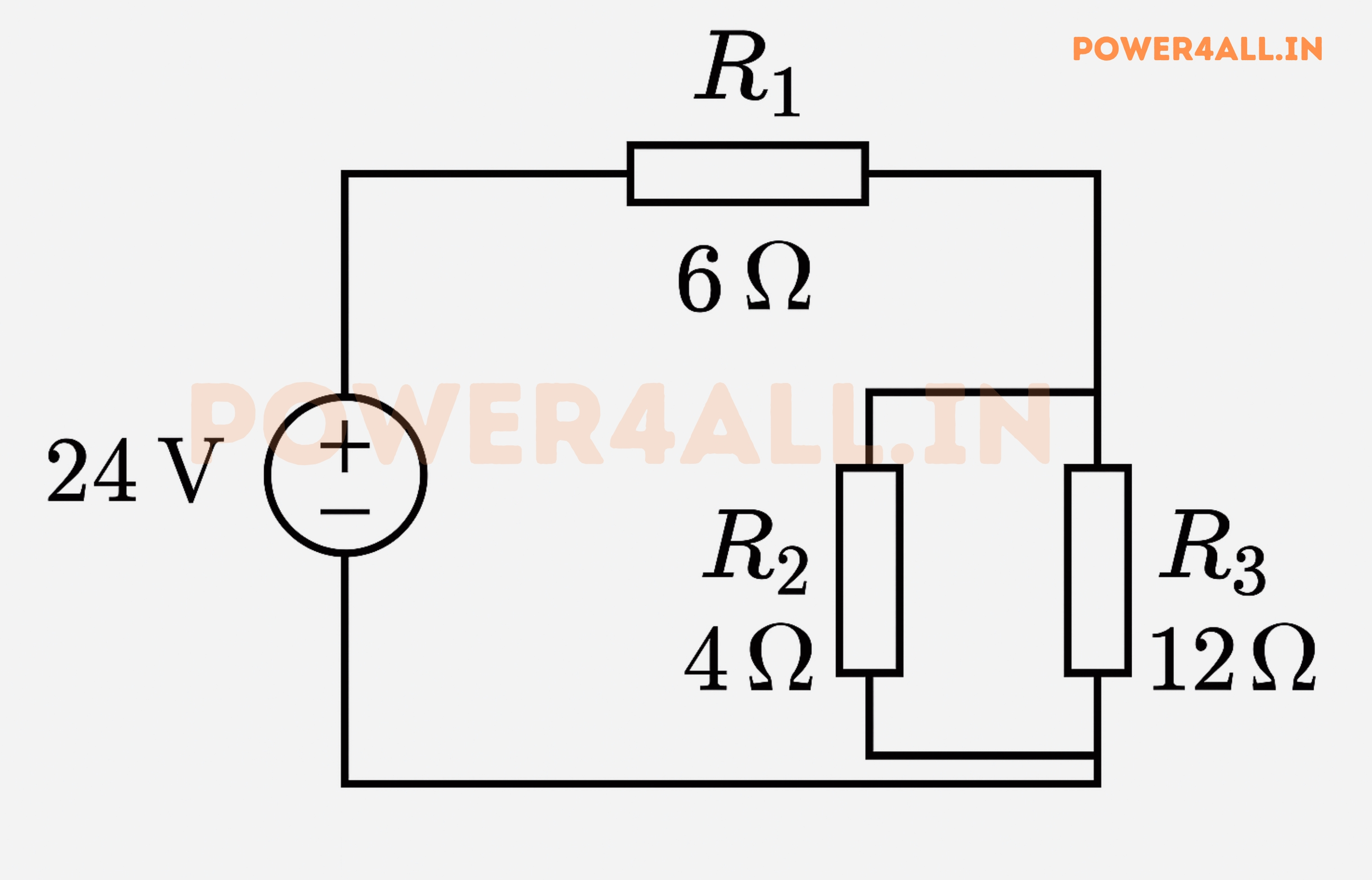
Example 1: Simple Series-Parallel Circuit
Problem Statement
Find the current through each resistor and the voltage across each component in the circuit shown below.
Given:
- Voltage source: V₁ = 24V
- Resistors: R₁ = 6Ω, R₂ = 4Ω, R₃ = 12Ω
- R₂ and R₃ are in parallel, then in series with R₁
Solution Method
Problem Solving Techniques
Mastering Kirchhoff's Laws requires systematic problem-solving approaches. This section provides step-by-step methodologies, common troubleshooting techniques, and strategies for tackling complex circuit analysis problems efficiently and accurately.
General Problem-Solving Strategy
The UNDERSTAND Method
A systematic approach to tackle any circuit analysis problem:
Common Problem Types and Approaches
Find Unknown Currents
Most common circuit analysis problem
Strategy
- Step 1: Assign current directions to all branches
- Step 2: Apply KCL at all but one node
- Step 3: Use Ohm's Law to relate voltages to currents
- Step 4: Solve the system of equations
- Step 5: Interpret negative results as opposite direction
Find Unknown Voltages
Voltage analysis and distribution problems
Strategy
- Step 1: Select ground reference node
- Step 2: Assign voltage variables to remaining nodes
- Step 3: Express branch currents in terms of node voltages
- Step 4: Apply KCL at each node
- Step 5: Solve for node voltages
Find Unknown Component Values
Design and reverse-engineering problems
Strategy
- Step 1: Use given operating conditions as constraints
- Step 2: Set up equations with unknown as variable
- Step 3: Apply Kirchhoff's Laws to relate unknowns to knowns
- Step 4: Solve for unknown component value
- Step 5: Check if result is physically reasonable
Advanced Problem-Solving Techniques
Sophisticated Analysis Methods
Superposition Principle
For linear circuits with multiple sources, analyze one source at a time with others turned off (voltage sources shorted, current sources opened).
Thevenin and Norton Equivalent Circuits
Simplify complex networks to single source and impedance for easier analysis of load effects.
Thevenin Equivalent
Steps to Find Thevenin Equivalent
- Vth: Open-circuit voltage at load terminals
- Rth: Resistance seen from terminals with sources zeroed
- Result: Voltage source Vth in series with Rth
Norton Equivalent
Steps to Find Norton Equivalent
- In: Short-circuit current at load terminals
- Rn: Same as Rth (resistance with sources zeroed)
- Result: Current source In in parallel with Rn
Source Transformation
Convert between voltage and current source representations to simplify analysis.
Vs = Is × Rs, Is = Vs / Rs
Voltage source ↔ Current source conversion
Troubleshooting Circuit Problems
Common Mistakes and How to Avoid Them
Frequently Asked Questions About BJTs
Common questions about Kirchhoff's Current Law (KCL) and Voltage Law (KVL), circuit analysis, and problem-solving — answered with practical insights for students and engineers.
Basic Operation and Theory
Q: What's the difference between KCL and KVL, and when do I use each?
Ans: KCL (Current Law) deals with current conservation at nodes/junctions, while KVL (Voltage Law) deals with energy conservation around closed loops.
- Use KCL when: You need to find unknown currents, analyze current distribution, or apply nodal analysis
- Use KVL when: You need to find unknown voltages, analyze voltage drops, or apply mesh analysis
- Use both when: Solving complex circuits with multiple unknowns
In practice, most circuit analysis uses both laws together to create a complete system of equations.
Q: Why do I get negative values when solving circuit problems? Did I make a mistake?
Ans: Negative values are often correct! They simply mean your assumed direction was opposite to the actual direction.
- Negative current: Current flows opposite to your assumed arrow direction
- Negative voltage: Polarity is opposite to your assumed + and - markings
- What to do: Keep the magnitude, but understand the actual direction is reversed
Example: If you calculate I = -2A, the actual current is 2A flowing in the opposite direction to your assumption. This is completely valid and correct.
Q: Do Kirchhoff's Laws work for AC circuits with different frequencies?
Ans: Yes, but with important modifications:
- Use complex phasors: Voltages and currents become complex numbers with magnitude and phase
- Impedance replaces resistance: Z = R + jX where X includes reactive components
- Instantaneous form: Laws apply at every instant in time
- RMS/phasor form: Laws apply to RMS values and phasor relationships
Frequency limitations: At very high frequencies (GHz range), distributed effects and electromagnetic wave propagation must be considered, requiring more advanced analysis methods.
Q: How do dependent sources affect Kirchhoff's Laws analysis?
Ans: Dependent sources require special treatment:
- Apply KCL and KVL normally: Dependent sources still follow the fundamental laws
- Express the dependency: Write the dependent source value in terms of the controlling variable
- Solve the system: Include the dependency relationship as an additional constraint
Example: Current-controlled voltage source (CCVS) with gain k:
- Vs = k × Icontrol (dependency relationship)
- Apply KVL: V1 + Vs + V2 = 0
- Substitute: V1 + k×Icontrol + V2 = 0
- Express Icontrol in terms of other circuit variables
Q: What happens to Kirchhoff's Laws in nonlinear circuits with diodes and transistors?
Ans:Kirchhoff's Laws still apply, but solution methods change:
- Laws remain valid: Current and voltage conservation still hold
- Linear relationships break: Ohm's Law doesn't apply to nonlinear elements
- Iterative solutions: Use Newton-Raphson or other numerical methods
- Approximation methods: Piecewise linear models, small-signal analysis
Practical approaches:
- Diode circuits: Assume forward voltage drop (0.7V for silicon)
- Transistor circuits: Use appropriate models (Ebers-Moll, small-signal)
- SPICE simulation: Computer tools handle the nonlinear math automatically
Q: How many equations do I need to solve a circuit completely?
Ans: Number of equations must equal number of unknowns:
- Count unknowns: Unknown currents, voltages, or component values
- Independent KCL equations: Number of nodes - 1
- Independent KVL equations: Number of independent loops
- Component relationships: Ohm's Law for each resistor
General formula for networks:
- Total equations needed: Number of branches (currents to find)
- KCL equations: n - 1 (where n = number of nodes)
- KVL equations: b - n + 1 (where b = number of branches)
Tip: If you have more equations than unknowns, some equations are dependent (redundant).
Q: Can I use Kirchhoff's Laws for circuits with transformers and mutual inductance?
Ans: Yes, with modifications for magnetic coupling:
- Basic laws apply: Current and voltage conservation remain valid
- Mutual inductance: Creates voltage coupling between separate loops
- Modified KVL: Include mutually induced voltages in loop equations
Transformer analysis:
- Primary side: V1 = L1(di1/dt) + M(di2/dt)
- Secondary side: V2 = L2(di2/dt) + M(di1/dt)
- Ideal transformer: V2/V1 = N2/N1, I1/I2 = N2/N1
Practical approach: Use equivalent circuit models or ideal transformer relationships to simplify analysis.
Q: Why don't my calculated values match my measured values exactly?
Ans: Real-world factors cause differences between theory and practice:
Component Tolerances
- Resistor tolerance: ±1%, ±5%, ±10% typical variations
- Capacitor tolerance: ±10%, ±20% common
- Component aging: Values drift over time
Measurement Limitations
- Meter accuracy: ±1% typical for handheld meters
- Loading effects: Meter resistance affects circuit
- Temperature effects: Component values change with temperature
Parasitic Effects
- Wire resistance: Especially significant in high-current circuits
- Contact resistance: Connection points add resistance
- Stray capacitance and inductance: Affects high-frequency behavior
Typical agreement: Within 5-10% is excellent for hand calculations vs. measurements.
Conclusion: Mastering Kirchhoff's Laws
Kirchhoff's Laws are more than just academic concepts - they're the fundamental principles that govern every electrical system around us. From the simple flashlight to complex power grids, these laws provide the mathematical foundation for understanding, analyzing, and designing electrical circuits.