Complete Ohm's Law Mastery Guide
Master the fundamental law of electricity - voltage, current, and resistance relationships with practical examples and real-world applications
Complete Learning Path - Ohm's Law Fundamentals to Applications
Navigate through comprehensive coverage of Ohm's Law from basic principles to advanced applications
What is Ohm's Law?
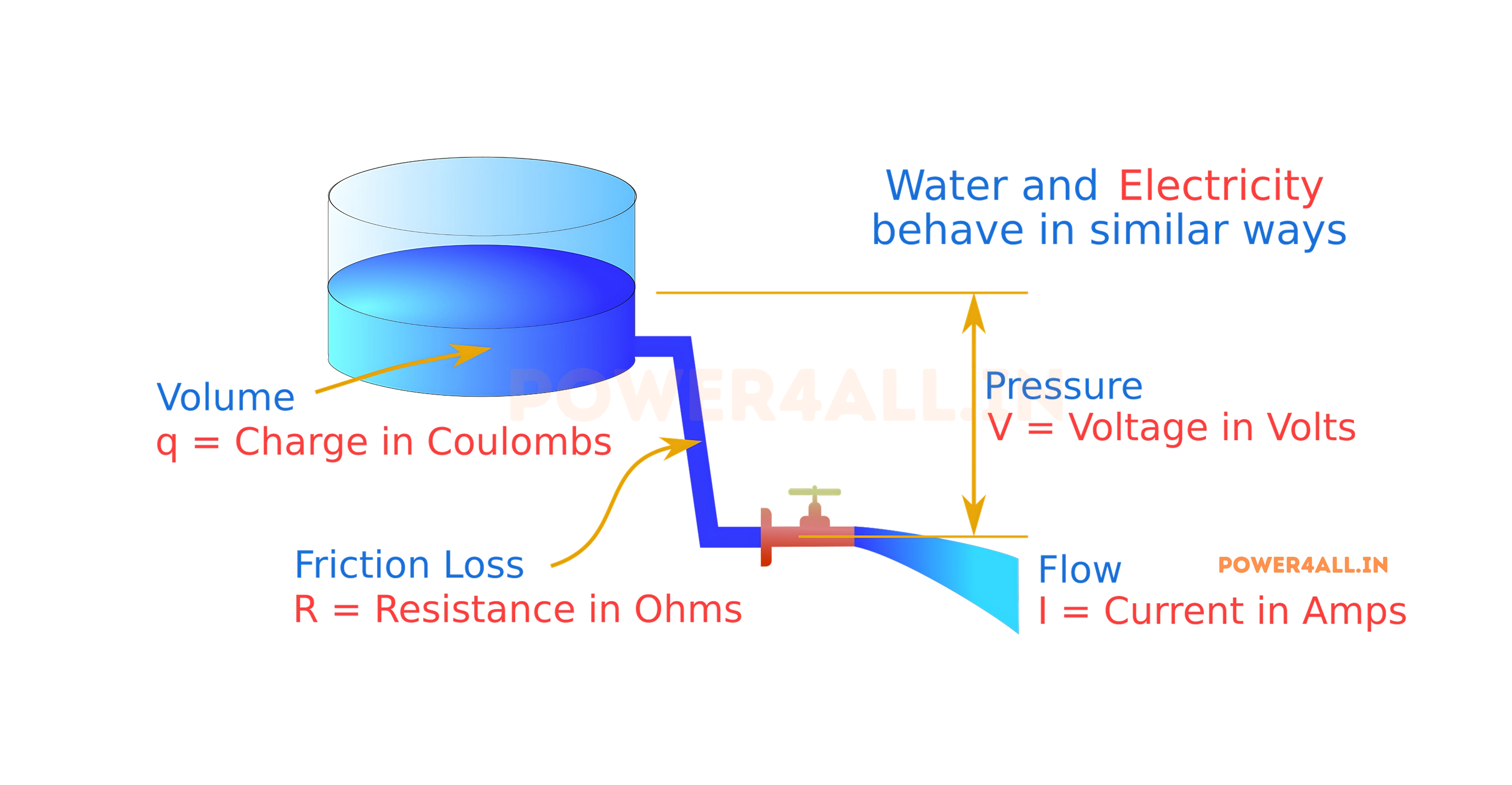
The Water Pipe Analogy
Think of electricity like water flowing through pipes. Voltage is like water pressure, current is like the flow rate of water, and resistance is like the diameter of the pipe - narrower pipes resist flow more than wider ones.
Perfect Comparison
- Water pressure → Voltage (V)
- Water flow rate → Current (I)
- Pipe diameter → Resistance (R)
- Flow control valve → Variable resistor
V = I × R
Voltage equals Current times Resistance
Why Ohm's Law is Essential
Ohm's Law is the cornerstone of electrical engineering and electronics. It allows us to predict and control electrical behavior, design circuits, troubleshoot problems, and ensure safe operation of electrical systems. Every electrical device you use daily operates according to this fundamental principle.
Circuit Design
Engineers use Ohm's Law to calculate proper component values, ensuring circuits work safely and efficiently within design specifications.
Troubleshooting
Technicians apply Ohm's Law to diagnose electrical problems by measuring voltages and currents to identify faulty components.
Safety Analysis
Ohm's Law helps determine safe operating conditions and current limits to prevent overheating and electrical hazards.
Power Calculations
Combined with power formulas, Ohm's Law enables accurate energy consumption calculations and efficiency analysis.
Historical Background
Georg Simon Ohm (1789-1854)
- Discovery: Formulated the law in 1827 through careful experimentation
- Initial reception: His work was initially criticized by the scientific community
- Recognition: Later recognized as fundamental to electrical science
- Legacy: The unit of electrical resistance (ohm) is named in his honor
- Impact: Laid the foundation for modern electrical engineering
Did You Know?
Ohm's Law applies to DC circuits and most AC circuits, but there are exceptions. Some materials and components don't follow Ohm's Law - these are called "non-ohmic" devices. Examples include diodes, transistors, and some gas-discharge tubes where the relationship between voltage and current is not linear.
Ohm's Law Fundamentals: Understanding the Relationship
To master Ohm's Law, you need to understand the three fundamental electrical quantities: voltage, current, and resistance. Each plays a unique role in electrical circuits, and their relationship forms the basis of all electrical calculations.
The Three Forms of Ohm's Law
Calculating Voltage
When you know current and resistance
V = I × R
Voltage = Current × Resistance
When to Use
- Determining voltage drop across a resistor
- Calculating supply voltage needed
- Finding voltage across circuit components
- Designing power supplies
Example
A 100Ω resistor carries 0.5A current:
- V = I × R = 0.5A × 100Ω = 50V
- The voltage across the resistor is 50 volts
Calculating Current
When you know voltage and resistance
I = V ÷ R
Current = Voltage ÷ Resistance
When to Use
- Determining current flow in circuits
- Checking if components are within current ratings
- Calculating fuse or breaker requirements
- Analyzing power consumption
Example
A 12V battery connected to a 4Ω resistor:
- I = V ÷ R = 12V ÷ 4Ω = 3A
- The current flowing is 3 amperes
Calculating Resistance
When you know voltage and current
R = V ÷ I
Resistance = Voltage ÷ Current
When to Use
- Finding unknown resistance values
- Troubleshooting circuit problems
- Determining component specifications
- Calculating equivalent resistance
Example
A circuit with 24V and 2A current:
- R = V ÷ I = 24V ÷ 2A = 12Ω
- The total resistance is 12 ohms
Units of Measurement
Standard Electrical Units and Their Relationships
Primary Units
| Quantity | Unit Name | Symbol | Definition | Named After |
|---|---|---|---|---|
| Voltage | Volt | V | Electric potential difference | Alessandro Volta |
| Current | Ampere (Amp) | A | Electric current flow | André-Marie Ampère |
| Resistance | Ohm | Ω | Opposition to current flow | Georg Simon Ohm |
| Power | Watt | W | Rate of energy transfer | James Watt |
Common Prefixes
Smaller Units
milli (m): 1/1000 (0.001)
micro (μ): 1/1,000,000 (0.000001)
nano (n): 1/1,000,000,000
Larger Units
kilo (k): 1,000
mega (M): 1,000,000
giga (G): 1,000,000,000
Examples
5 mA = 0.005 A
2.2 kΩ = 2,200 Ω
120 mV = 0.12 V
Practical Usage
Use appropriate units for easier calculations and clearer communication in technical specifications.
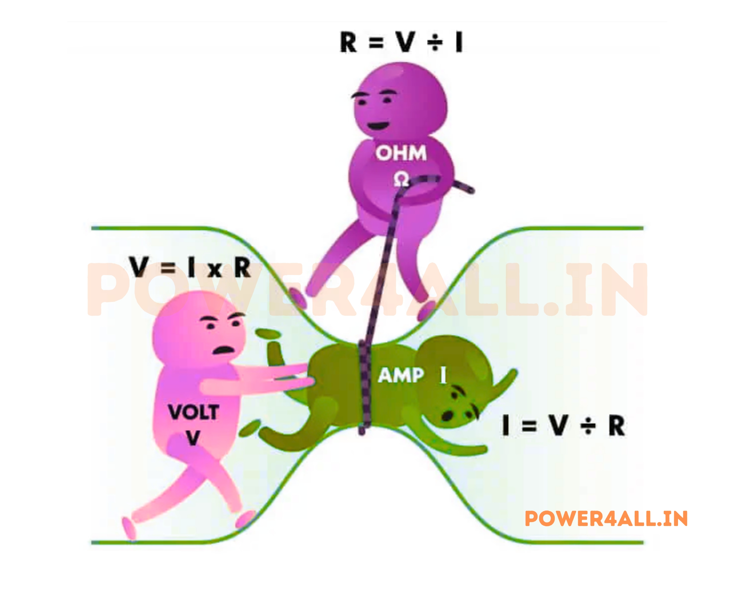
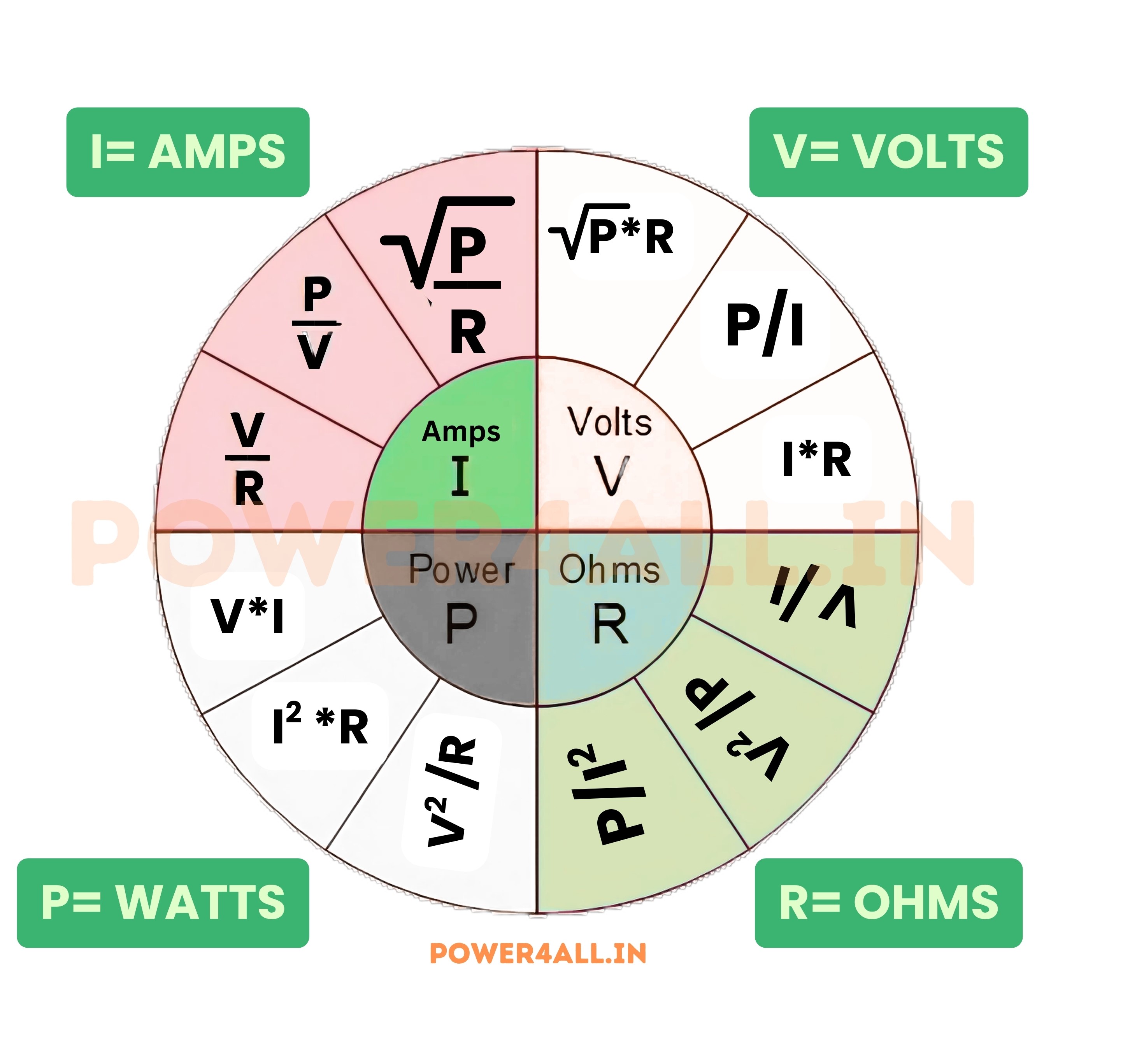
The Ohm's Law Triangle: Your Memory Tool
The Ohm's Law triangle is a simple visual tool that helps you remember which formula to use for any calculation. By covering the unknown quantity, the triangle shows you exactly how to calculate it using the other two known values.
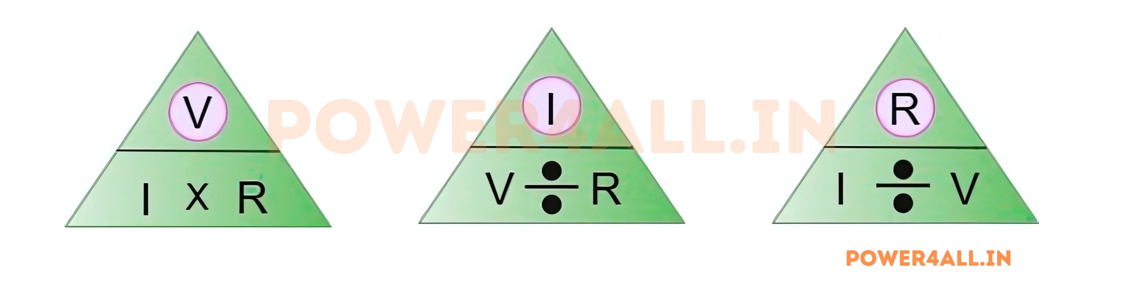
How to Use the Triangle
The triangle is divided into three sections: V at the top, I and R at the bottom. To find any unknown value, simply cover that letter and perform the operation shown by the remaining letters.
Triangle Applications with Examples
Finding Voltage
Cover V in the triangle
Example Problem
A circuit has a current of 2A flowing through a 6Ω resistor. What is the voltage?
- Cover V in the triangle
- See I × R remaining
- Calculate: V = I × R = 2A × 6Ω = 12V
- Answer: The voltage is 12 volts
Finding Current
Cover I in the triangle
Example Problem
A 9V battery is connected to a 3Ω resistor. What current flows?
- Cover I in the triangle
- See V over R remaining
- Calculate: I = V ÷ R = 9V ÷ 3Ω = 3A
- Answer: The current is 3 amperes
Finding Resistance
Cover R in the triangle
Example Problem
A circuit with 15V produces 5A of current. What is the resistance?
- Cover R in the triangle
- See V over I remaining
- Calculate: R = V ÷ I = 15V ÷ 5A = 3Ω
- Answer: The resistance is 3 ohms
Memory Techniques
Visual Memory
Remember: "Voltage is always on top" - just like voltage is the driving force in circuits.
Practice Method
Draw the triangle repeatedly until you can visualize it instantly when needed.
Quick Check
Always verify your answer makes sense - higher resistance should mean lower current for same voltage.
Unit Check
Ensure your final answer has the correct units: volts (V), amperes (A), or ohms (Ω).
Pro Tip
The triangle method works for any formula with three variables where one equals the product or quotient of the other two. You can apply this technique to power formulas (P = V × I) and many other electrical relationships!
Understanding Voltage, Current & Resistance
To truly master Ohm's Law, you need a deep understanding of each electrical quantity. Voltage, current, and resistance each have unique characteristics, measurement methods, and practical implications in electrical circuits.
Voltage (V) - The Electrical Pressure
What is Voltage?
Voltage is the electrical potential difference between two points. It's the force that pushes electrons through a circuit, similar to how water pressure pushes water through pipes.
Key Characteristics
- Measured between two points: Always relative, not absolute
- Driving force: Causes current to flow in circuits
- Energy per charge: Joules per coulomb
- Polarity matters: Has positive and negative terminals
Common Voltage Levels
- AA Battery: 1.5V DC
- Car Battery: 12V DC
- Household Outlet: 120V/240V AC
- USB Port: 5V DC
- Phone Charger: 3.7V - 20V DC
- High Voltage Lines: 115kV - 765kV AC
Voltage Types and Sources
DC vs AC Voltage and Common Sources
| Voltage Type | Characteristics | Common Sources | Applications |
|---|---|---|---|
| DC (Direct Current) | Constant polarity, steady value | Batteries, solar panels, DC power supplies | Electronics, electric vehicles, LED lighting |
| AC (Alternating Current) | Changing polarity, sinusoidal waveform | Power plants, generators, transformers | Home power, industrial motors, transmission |
| Pulsating DC | DC with AC ripple component | Rectified AC, switching power supplies | Power supply outputs, charging circuits |
| Square Wave | Rapidly switching between levels | Digital circuits, PWM controllers | Digital systems, motor speed control |
Current (I) - The Flow of Electrons
Understanding Electric Current
Current is the flow of electric charge through a conductor
Current Fundamentals
- Definition: Charge flow rate (coulombs per second)
- Direction: Conventional current flows from + to -
- Electron flow: Actual electrons move from - to +
- Measurement: Ammeter in series with circuit
I = Q ÷ t
Current = Charge ÷ Time
Current Magnitudes
Current levels in different applications
| Application | Typical Current |
|---|---|
| LED | 20 mA |
| Smartphone charging | 1-3 A |
| Household appliances | 5-15 A |
| Electric car motor | 100-400 A |
| Lightning bolt | 30,000 A |
Resistance (R) - Opposition to Current Flow
What Creates Resistance
Resistance occurs when electrons collide with atoms in a conductor. More collisions mean higher resistance and reduced current flow.
Temperature Effects
Most materials have higher resistance when hot. This is why incandescent bulbs draw more current when cold.
Physical Factors
Resistance depends on material type, length (longer = more resistance), and cross-sectional area (thicker = less resistance).
Practical Applications
Resistors control current, create voltage drops, limit current to protect components, and convert electrical energy to heat.
Material Resistance Comparison
Resistivity of common materials (at room temperature):
- Silver: Best conductor (1.6 × 10⁻⁸ Ω⋅m)
- Copper: Excellent conductor (1.7 × 10⁻⁸ Ω⋅m)
- Aluminum: Good conductor (2.8 × 10⁻⁸ Ω⋅m)
- Carbon: Moderate conductor (3.5 × 10⁻⁵ Ω⋅m)
- Glass: Excellent insulator (10¹² Ω⋅m)
- Rubber: Good insulator (10¹³ Ω⋅m)
Calculations & Examples: Solving Real Problems
The best way to master Ohm's Law is through practice with real-world examples. These calculations demonstrate how to apply the law in practical situations you'll encounter in electronics and electrical work.
Basic Calculations
LED Current Limiting
Calculating resistor value for LED protection
Problem
An LED has a forward voltage of 2V and maximum current of 20mA. What resistor is needed with a 5V supply?
Battery Life Calculation
Determining how long a battery will last
Problem
A 1000mAh battery powers a 20Ω load at 6V. How long will it last?
Household Circuit Analysis
Understanding home electrical circuits
Problem
A 1500W hair dryer is plugged into a 120V outlet. What current does it draw?
Advanced Problem Solving
Complex Circuits and Multi-Step Calculations
Series Circuit Analysis
Series Circuit Problem
Three resistors (10Ω, 20Ω, 30Ω) are connected in series with a 12V battery. Find all currents and voltages.
Parallel Circuit Analysis
Parallel Circuit Problem
Two resistors (6Ω and 12Ω) are connected in parallel across a 24V source. Find all currents.
Practical Calculation Tips
Units Consistency
Always use consistent units: volts, amperes, and ohms. Convert prefixes (mA to A, kΩ to Ω) before calculating.
Significant Figures
Round answers appropriately based on measurement precision. Engineering values typically use 2-3 significant figures.
Verify Results
Check your answer by working backwards or using alternative methods. Does the result make physical sense?
Safety Margins
In real applications, use components rated 20-50% above calculated values for reliability and safety.
Practical Applications: Ohm's Law in the Real World
Ohm's Law is not just a theoretical concept—it's a practical tool used daily in electronics design, troubleshooting, and electrical work. Understanding these applications helps you see how fundamental this law is to modern technology.
Electronics and Circuit Design
Microcontroller Circuits
Designing interfaces for microcontrollers and sensors
Common Applications
- Pull-up resistors: Ensure defined logic levels (typically 10kΩ)
- Current limiting: Protect GPIO pins (typically 3.3V/5V logic)
- Sensor interfaces: Voltage dividers for analog inputs
- Status LEDs: Visual indicators with current limiting
Arduino LED Interface
Connecting an LED to Arduino 5V output pin:
- LED forward voltage: 2.1V (red LED)
- Desired current: 10mA (safe for LED and Arduino)
- Resistor needed: R = (5V - 2.1V) ÷ 0.01A = 290Ω
- Standard value: Use 330Ω (gives ~8.8mA, perfectly safe)
Consumer Electronics
How Ohm's Law enables everyday devices
Device Applications
- Phone chargers: Current limiting for safe battery charging
- Audio systems: Volume controls using variable resistors
- Displays: Backlight current control and dimming
- Touch screens: Voltage dividers for position sensing
Phone Charging Analysis
USB-C fast charger analysis:
- Output voltage: 20V (USB PD)
- Output current: 3A maximum
- Cable resistance: ~0.2Ω total
- Voltage drop: V = I × R = 3A × 0.2Ω = 0.6V
- Delivered voltage: 20V - 0.6V = 19.4V at device
Automotive Electronics
Vehicle electrical systems and diagnostics
Automotive Applications
- Headlight circuits: Current calculations for bulb replacement
- Sensor circuits: Temperature and pressure sensor interfaces
- Charging systems: Alternator and battery system analysis
- Diagnostic codes: Electrical fault detection and analysis
Headlight Upgrade Calculation
Upgrading from halogen to LED headlights:
- Original halogen: 55W at 12V = 4.6A current
- LED replacement: 25W at 12V = 2.1A current
- Wire capacity: Existing wire easily handles reduced current
- Fuse rating: No change needed (current decreased)
Power Systems and Industrial Applications
Large-Scale Electrical Systems and Industrial Equipment
Power Distribution
| Application | Voltage Level | Ohm's Law Usage | Key Considerations |
|---|---|---|---|
| Household wiring | 120V/240V | Load calculations, wire sizing | Safety codes, circuit protection |
| Industrial motors | 480V/600V | Starter sizing, protection settings | Power factor, motor characteristics |
| Distribution lines | 4kV-35kV | Line loss calculations, load flow | Voltage regulation, efficiency |
| Transmission lines | 115kV-765kV | Conductor sizing, loss analysis | Corona effects, line parameters |
Industrial Equipment Examples
Motor Control
Calculate starting currents, select proper contactors and overload protection based on motor ratings and supply voltage.
Heating Elements
Design industrial heaters by calculating resistance needed for specific power output at available voltage.
Arc Welding
Control welding current by adjusting resistance in welding circuits, ensuring proper heat for different materials.
Battery Systems
Calculate charging currents and times for large battery banks in UPS and renewable energy systems.
Home and DIY Applications
Home Electrical Projects
Safe electrical work around the house
Adding a New Outlet
Determining if existing circuit can handle additional load:
- Check circuit breaker: 15A or 20A rating
- Measure existing load: Use clamp meter on hot wire
- Calculate new load: P ÷ V = I for new device
- Total current: Existing + new load
- Safety margin: Keep total under 80% of breaker rating
Workshop and Garage
Power tools and equipment sizing
Extension Cord Selection
Choosing the right extension cord for a 15A circular saw:
- Tool requirement: 15A at 120V
- 50ft cord resistance: ~0.4Ω for 12 AWG wire
- Voltage drop: V = I × R = 15A × 0.4Ω = 6V
- Tool voltage: 120V - 6V = 114V (acceptable)
- Recommendation: Use 12 AWG or thicker for long runs
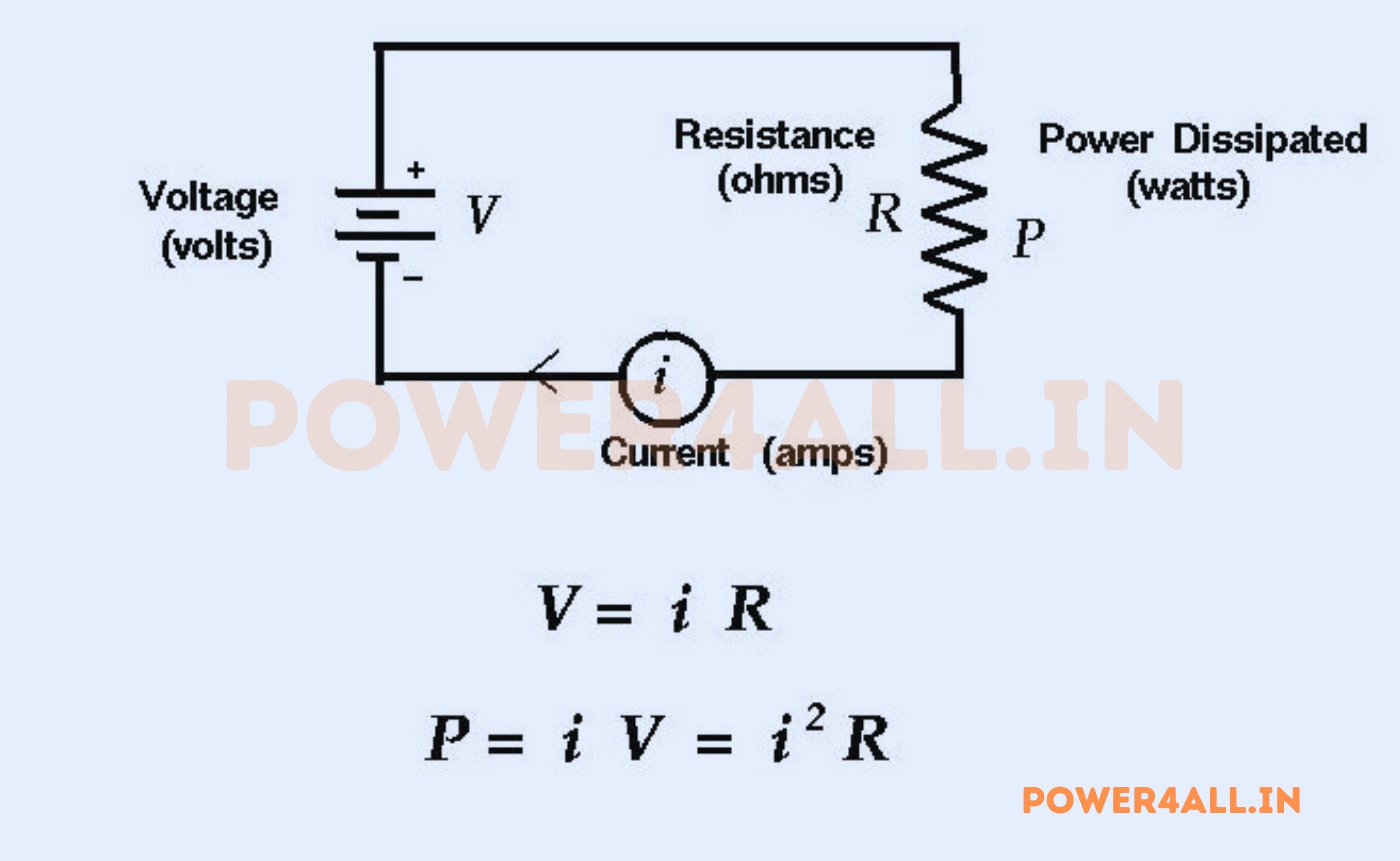
Power Relationships: Extending Ohm's Law
Power is the rate of energy transfer in electrical circuits. By combining Ohm's Law with power formulas, we can solve complex problems involving energy consumption, heat generation, and system efficiency.
The Power Triangle
Understanding Electrical Power
Power represents how quickly electrical energy is converted to other forms like heat, light, or mechanical energy. It's measured in watts (W).
P = V × I
Power = Voltage × Current
Extended Power Formulas
- P = V × I (basic power formula)
- P = I² × R (using Ohm's Law substitution)
- P = V² ÷ R (using Ohm's Law substitution)
Power Formula Selection
Choose the formula based on known values:
- Know V and I: Use P = V × I
- Know I and R: Use P = I² × R
- Know V and R: Use P = V² ÷ R
- All give the same result!
Power Calculations in Practice
Heat Generation
Calculating thermal effects in circuits
Resistor Power Rating
A 470Ω resistor carries 20mA. What power rating is needed?
Energy Consumption
Calculating electricity costs and usage
Monthly Electric Bill
A 1500W space heater runs 6 hours daily. What's the monthly cost at $0.12/kWh?
Battery Capacity
Determining runtime and charging requirements
Solar System Sizing
A 12V system draws 5A continuously. Size the battery for 24-hour backup.
Efficiency and Loss Calculations
Power Loss Analysis and System Efficiency
Transmission Line Losses
Power Line Efficiency
A transmission line has 2Ω resistance and carries 100A. What power is lost?
Heat Dissipation Requirements
Thermal Management
Power dissipated as heat requires proper cooling. Every watt must be removed to prevent overheating.
Heat Sinks
Size heat sinks based on power dissipation and thermal resistance. Higher power needs larger heat sinks or fans.
Derating
Component power ratings decrease with temperature. Operate at 50-80% of rating for reliability.
Safety Factors
Always include margins for unexpected conditions, component tolerance, and aging effects.
Power and Energy Distinction
Power (watts) is the instantaneous rate of energy consumption, while energy (watt-hours) is power consumed over time. Your electric meter measures energy (kWh), but your appliances are rated in power (kW). Understanding this distinction is crucial for energy calculations and cost analysis.
Circuit Analysis with Ohm's Law
Ohm's Law is the foundation for analyzing electrical circuits. Whether dealing with simple series and parallel circuits or complex networks, understanding how to apply Ohm's Law systematically allows you to solve any resistive circuit.
Series Circuits
Series Circuit Characteristics
In series circuits, components are connected end-to-end in a single path. Current is the same through all components, but voltage divides proportionally.
Key Properties
- Same current: I₁ = I₂ = I₃ = I_total
- Voltage adds: V_total = V₁ + V₂ + V₃
- Resistance adds: R_total = R₁ + R₂ + R₃
- Voltage divider: V_x = (R_x ÷ R_total) × V_source
Series Circuit Example
Three 100Ω resistors in series with 15V source:
- Total resistance: 300Ω
- Total current: 15V ÷ 300Ω = 0.05A
- Voltage across each: 0.05A × 100Ω = 5V
- Check: 5V + 5V + 5V = 15V ✓
Parallel Circuits
Parallel Circuit Properties
Multiple paths for current flow
Key Characteristics
- Same voltage: V₁ = V₂ = V₃ = V_source
- Current divides: I_total = I₁ + I₂ + I₃
- Reciprocal resistance: 1/R_total = 1/R₁ + 1/R₂ + 1/R₃
- Current divider: I_x = (R_total ÷ R_x) × I_total
Parallel Calculation
Two resistors: 6Ω and 3Ω in parallel:
- 1/R_total = 1/6 + 1/3 = 1/6 + 2/6 = 3/6
- R_total = 6/3 = 2Ω
- Rule: Always less than smallest resistor
Current Divider Analysis
How current splits in parallel branches
Current Division Example
12V source with 4Ω and 12Ω resistors in parallel:
Series-Parallel Combination Circuits
Analyzing Complex Resistor Networks
Step-by-Step Analysis Method
Complex Circuit Example
A 24V source feeds a circuit with R1 (6Ω) in series with parallel combination of R2 (12Ω) and R3 (4Ω). Find all currents and voltages.
Voltage and Current Divider Rules
Voltage Divider
In series circuits: V_x = (R_x ÷ R_total) × V_source. Larger resistors get proportionally more voltage.
Current Divider
In parallel circuits: I_x = (R_total ÷ R_x) × I_total. Smaller resistors get proportionally more current.
Quick Calculations
These rules provide shortcuts for finding specific values without calculating everything step by step.
Design Applications
Use divider rules to design circuits with specific voltage or current ratios for sensors and controls.
Troubleshooting with Ohm's Law
Ohm's Law is an essential tool for diagnosing electrical problems. By measuring any two of the three quantities (voltage, current, resistance) and calculating the third, you can identify faults, verify proper operation, and ensure circuit safety.
Diagnostic Techniques
Identifying Open Circuits
When current flow is interrupted
Symptoms of Open Circuits
- No current flow: Ammeter reads zero
- Full source voltage: Appears across the open
- No voltage drop: Across other components
- Device doesn't operate: Lights off, motors stopped
Open Circuit Diagnosis
A 12V circuit with 100Ω load should draw 0.12A but shows 0A:
- Expected current: I = 12V ÷ 100Ω = 0.12A
- Measured current: 0A (indicates open circuit)
- Voltage measurement: Full 12V across the break
- Diagnosis: Broken wire, blown fuse, or failed component
- Solution: Locate and repair the break
Detecting Short Circuits
When resistance is abnormally low
Symptoms of Short Circuits
- Excessive current: Much higher than calculated
- Low or zero voltage: Across the shorted component
- Blown fuses: Overcurrent protection operates
- Overheating: Wires, components get hot
Short Circuit Analysis
A motor rated for 5A at 120V is drawing 25A:
- Normal resistance: R = 120V ÷ 5A = 24Ω
- Actual resistance: R = 120V ÷ 25A = 4.8Ω
- Diagnosis: Internal short in motor windings
- Action: Immediately disconnect power to prevent damage
High Resistance Problems
When resistance is higher than expected
Causes of High Resistance
- Corrosion: Oxidation on connections
- Loose connections: Poor contact resistance
- Damaged components: Partially failed resistors
- Temperature effects: Heating increasing resistance
High Resistance Diagnosis
A 100W bulb at 120V should draw 0.83A but only draws 0.6A:
- Expected resistance: R = 120²V ÷ 100W = 144Ω
- Actual resistance: R = 120V ÷ 0.6A = 200Ω
- Extra resistance: 200Ω - 144Ω = 56Ω
- Likely cause: Poor connection or voltage drop in wiring
Systematic Troubleshooting Process
Step-by-Step Electrical Diagnosis
The SAFER Method
Measurement Strategies
| Measurement | When to Use | Connection Method | Safety Notes |
|---|---|---|---|
| Voltage | Check power supply, voltage drops | Parallel to component | Can be measured with power on |
| Current | Verify load operation, find shorts | Series with circuit | Use clamp meter to avoid breaking circuit |
| Resistance | Check component values, find opens | Across de-energized component | MUST turn off power first |
| Continuity | Verify connections, find breaks | Between connection points | Power off, check for stored energy |
Common Troubleshooting Scenarios
Dim Lights
Cause: Voltage drop due to high resistance connections or undersized wiring. Fix: Check and tighten connections, verify wire capacity.
Overheating Wires
Cause: Current exceeding wire capacity, often due to overloaded circuits. Fix: Reduce load or upgrade wire size.
Blown Fuses
Cause: Overcurrent from shorts or overloads. Fix: Find and eliminate the fault before replacing fuse.
Battery Drain
Cause: Parasitic current draw when system should be off. Fix: Measure current with system off, isolate cause.
Safety Considerations When Applying Ohm's Law
Understanding Ohm's Law is not just about calculations—it's about working safely with electricity. Proper application of electrical principles ensures personal safety and prevents equipment damage.
Electrical Safety Fundamentals
Critical Safety Warning
Electricity can be lethal even at relatively low voltages. Current as low as 0.001 amperes (1 milliampere) can be felt, and 0.005 amperes can be painful. Currents above 0.010 amperes can cause muscle paralysis, preventing you from letting go of live conductors.
Physiological Effects of Current
How different current levels affect the human body
| Current Level | Effect on Human Body | Typical Resistance | Dangerous Voltage |
|---|---|---|---|
| 1 mA | Barely perceptible | 1000-100,000Ω | 1-100V |
| 5 mA | Maximum safe current | Dry skin: ~50,000Ω | 250V |
| 10-20 mA | Muscular control lost | Wet skin: ~1,000Ω | 10-20V |
| 50 mA | Possible ventricular fibrillation | Internal body: ~500Ω | 25V |
| 100-200 mA | Likely fatal | Hand to hand: ~1,000Ω | 100-200V |
Voltage Hazard Levels
Understanding voltage classifications and safety requirements
Standard Voltage Classifications
- Extra-low voltage (ELV): ≤50V AC, ≤120V DC (Generally safe to touch)
- Low voltage (LV): 50-1000V AC, 120-1500V DC (Dangerous, can be fatal)
- Medium voltage (MV): 1-35kV (High danger, specialized training required)
- High voltage (HV): >35kV (Extreme danger, arc flash risk)
Safety Calculation Example
Why is 120V household power dangerous?
- Typical body resistance: 1,000Ω (wet conditions)
- Current flow: I = 120V ÷ 1,000Ω = 0.12A = 120mA
- Result: Potentially lethal current level
- Safety measure: GFCI protection trips at 5mA
Personal Protective Equipment
Essential safety gear for electrical work
Basic PPE for Electrical Work
- Safety glasses: Protect eyes from arc flash and debris
- Insulated gloves: Rated for working voltage level
- Insulated tools: Prevent accidental contact with live circuits
- Arc-rated clothing: For high-energy electrical work
- Non-conductive footwear: Rubber soles, no metal
PPE Selection by Voltage
- ≤50V: Basic safety glasses, avoid jewelry
- 50-600V: Class 0 gloves, safety glasses, insulated tools
- 600V-17kV: Class 2 gloves, arc-rated clothing
- >17kV: Specialized HV equipment and training
Safe Working Practices
Procedures for Safe Electrical Work
The Five Safety Rules
Measurement Safety
Meter Selection
Use CAT-rated meters appropriate for the voltage level. CAT IV for service entrance, CAT III for distribution panels, CAT II for outlets.
One-Hand Rule
Keep one hand in your pocket when making measurements to avoid creating a current path across your chest and heart.
Visual Inspection
Always inspect test equipment before use. Look for damaged leads, cracked cases, or missing safety features.
Work with Others
Never work alone on electrical systems. Have a qualified person nearby who can provide emergency assistance.
Circuit Protection and Safety Devices
| Protection Device | Function | Ohm's Law Application | Typical Settings |
|---|---|---|---|
| Fuses | Overcurrent protection | I = P ÷ V to size fuse | 125% of normal load current |
| Circuit Breakers | Resettable overcurrent protection | Calculate trip current for loads | 80% loading of breaker rating |
| GFCI | Ground fault protection | Detects 5mA imbalance | Required in wet locations |
| AFCI | Arc fault protection | Detects dangerous arcing | Required in bedrooms, living areas |
Frequently Asked Questions About Ohm's Law
Here are the most common questions about Ohm's Law, covering everything from basic concepts to practical applications. These answers help clarify common misconceptions and provide practical guidance.
Basic Understanding Questions
Q: What exactly is Ohm's Law and why is it important?
A: Ohm's Law describes the fundamental relationship between voltage, current, and resistance in electrical circuits. It states that voltage equals current times resistance (V = I × R). This law is crucial because:
- Circuit design: Engineers use it to calculate proper component values
- Troubleshooting: Technicians apply it to diagnose electrical problems
- Safety: It helps predict dangerous current levels
- Energy efficiency: Used to calculate power consumption and losses
- Universal application: Works for DC circuits and resistive AC circuits
Without Ohm's Law, modern electrical engineering and electronics would be impossible. It's literally the foundation that allows us to understand and control electrical circuits.
Q: I'm confused about volts, amps, and ohms. Can you explain the difference?
A: Think of electricity like water flowing through pipes:
| Electrical Quantity | Water Analogy | What It Measures | Common Values |
|---|---|---|---|
| Voltage (Volts) | Water pressure | Electrical pressure/force | 1.5V (battery) to 120V (outlet) |
| Current (Amperes) | Water flow rate | Rate of electron flow | 0.02A (LED) to 15A (appliance) |
| Resistance (Ohms) | Pipe diameter/restrictions | Opposition to current flow | 1Ω (wire) to 1MΩ (insulator) |
Key relationships:
- Higher voltage → More current (if resistance stays same)
- Higher resistance → Less current (if voltage stays same)
- All three are always related by V = I × R
Q: How do I actually use the Ohm's Law triangle?
A: The triangle is a visual memory aid. Here's how to use it step by step:
Triangle Example
Find current when V = 12V and R = 4Ω:
- Cover I in the triangle
- See V over R remaining
- Formula: I = V ÷ R
- Calculate: I = 12V ÷ 4Ω = 3A
Practical Application Questions
Q: Does Ohm's Law work for all electrical circuits?
A: Ohm's Law works perfectly for:
- Resistive materials: Wire, heating elements, incandescent bulbs
- DC circuits: Batteries, DC power supplies
- AC resistive circuits: Heaters, some motors
- Linear components: Most basic electronic components
Ohm's Law has limitations with:
- Non-linear devices: Diodes, transistors, LEDs
- Reactive components: Capacitors, inductors (in AC)
- Temperature-sensitive devices: Thermistors, bulb filaments when heating
- Gas-discharge devices: Fluorescent lights, neon signs
For AC circuits: Use impedance (Z) instead of resistance, but the relationship V = I × Z still applies.
Q: How can I use Ohm's Law to work safely with electricity?
A: Ohm's Law is a critical safety tool:
Calculate Safe Current Levels
Safety Calculation
Why is 50V considered the safety threshold?
- Dry skin resistance: ~50,000Ω minimum
- Current at 50V: I = 50V ÷ 50,000Ω = 0.001A = 1mA
- Result: Just at the threshold of perception, generally safe
- Wet conditions: Resistance drops to ~1,000Ω, making even 10V dangerous
Verify Protective Device Settings
- Fuse sizing: Calculate expected current, size fuse 125% higher
- Wire capacity: Ensure wire can handle calculated current safely
- GFCI operation: Understand why 5mA trip level protects lives
- Arc flash analysis: Calculate incident energy for PPE selection
Troubleshooting Questions
Q: How do I use Ohm's Law to find problems in circuits?
A: Ohm's Law is your primary diagnostic tool:
Step-by-Step Troubleshooting
Common Diagnostic Scenarios
- No current flow: Check for open circuits (broken wires, blown fuses)
- Excessive current: Look for short circuits or reduced resistance
- Low voltage: Check for voltage drops due to high resistance connections
- Overheating: Calculate if current exceeds component ratings
Conclusion: Mastering the Foundation of Electrical Engineering
Congratulations! You've completed a comprehensive journey through Ohm's Law, from its fundamental principles to advanced applications. This knowledge forms the bedrock of electrical engineering and will serve you well in any electrical or electronics endeavor.
Key Takeaways
Universal Principle
Ohm's Law (V = I × R) is the fundamental relationship governing electrical circuits. Master this, and you understand the essence of electrical behavior.
Practical Tool
From designing circuits to troubleshooting problems, Ohm's Law provides the mathematical foundation for solving real-world electrical challenges.
Safety Foundation
Understanding the relationship between voltage, current, and resistance is essential for working safely with electricity and protecting both people and equipment.
Building Block
Ohm's Law is your stepping stone to advanced electrical concepts like AC analysis, power calculations, and complex circuit design.
Remember
Ohm's Law is more than just a formula—it's a way of thinking about electrical relationships. Whether you're designing the next breakthrough in electronics or simply trying to understand why a circuit isn't working, V = I × R will be your constant companion. Use this knowledge responsibly, always prioritize safety, and never stop learning!